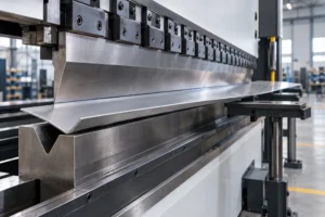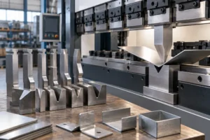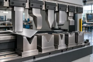
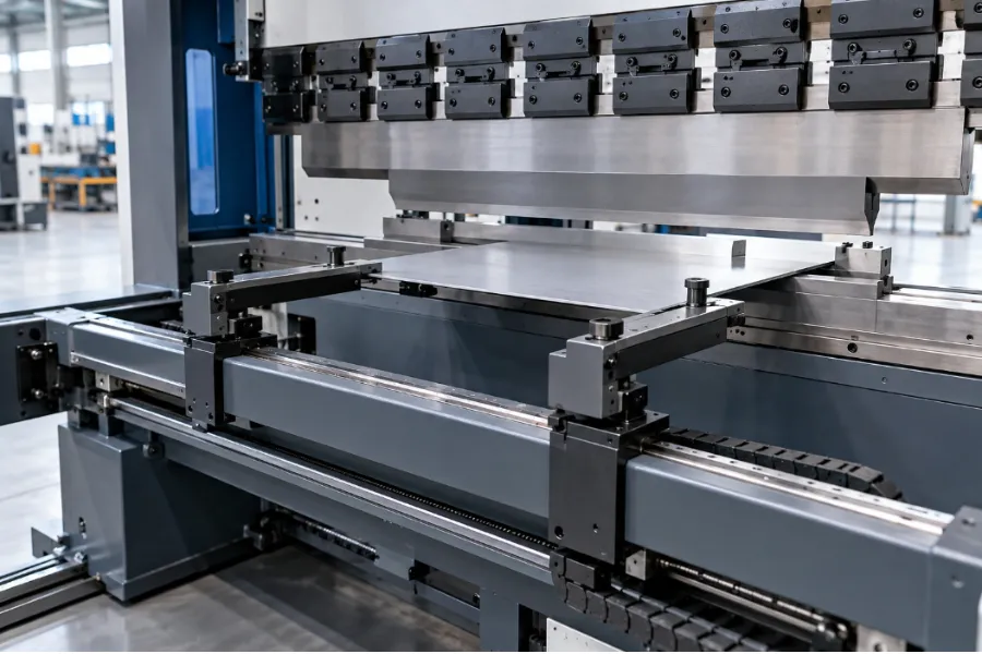
A press brake backgauge positions sheet metal relative to the punch and die before each bend. Its stop fingers create a repeatable reference that helps locate the bend line and control flange dimensions.
On a CNC press brake, the backgauge can reposition automatically as the bending program advances. Understanding the system requires three things: how it positions the workpiece, what each axis changes, and which movements the part actually requires.
What Is a Press Brake Backgauge?
A press brake backgauge, also written as back gauge, is the positioning system located behind the tooling. The operator places the workpiece against the backgauge fingers, also called backstop fingers, to establish its position before bending.
The basic relationship is:
Backgauge position → Workpiece position → Bend-line location → Flange dimension
The backgauge determines where the workpiece is positioned. The ram, tooling, material properties, and bending parameters determine how the material is formed.
A typical CNC press brake backgauge includes stop fingers, a supporting beam or frame, servo motors, ball screws or another transmission mechanism, linear guides, position feedback, and CNC control.
How Does a Press Brake Backgauge Work?
A CNC backgauge operates as part of the programmed bending sequence rather than as an isolated stop.
1. The CNC Defines the Target Position
Each bending step can contain the required backgauge coordinates. These positions depend on the part geometry, bend sequence, tooling arrangement, and reference edge.
For a straightforward flange, the X-axis normally provides the primary depth position.
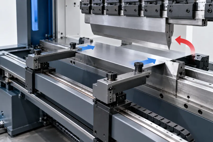
2. The Backgauge Moves Into Position
The CNC sends the target coordinates to the drive system. Servo motors and the transmission mechanism move the required axes until the backgauge reaches the programmed position.
Depending on the backgauge system, X, R, Z, or multiple axes may reposition automatically between bends.
3. The Workpiece Contacts the Backstop Fingers
The operator places the sheet against the fingers to establish a physical reference.
Both contact points must locate the workpiece correctly. If the sheet contacts only one finger or sits against them at an angle, the workpiece can become skewed relative to the bend line and produce unequal flange dimensions.
4. The Bend Is Made
Once the workpiece is positioned, the ram descends and the punch forms the material into the die.
This distinction matters when troubleshooting. An incorrect finished dimension does not automatically indicate a backgauge problem because tooling, bend calculations, material variation, and workpiece contact can also affect the result.
5. The Backgauge Retracts or Repositions
During forming, the workpiece rotates around the tooling and may move toward the backgauge. When programmed, the gauge can retract at the appropriate point in the bending cycle to provide clearance and reduce interference with the part.
For the next operation, the backgauge moves to the coordinates required by the next bending step and establishes a new reference.
Press Brake Backgauge Axes Explained
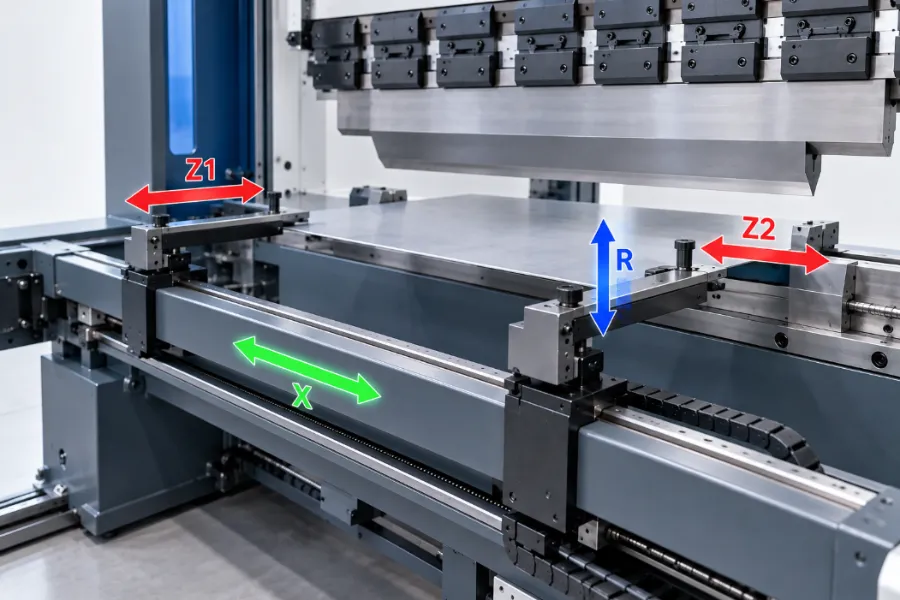
A backgauge axis represents an independently controlled direction of movement. Additional axes increase positioning freedom, but they should solve a specific gauging requirement rather than simply increase the advertised axis count.
| Axis | Movement | Main Function |
|---|---|---|
| X | Front/back | Controls gauging depth |
| R | Up/down | Controls gauging height and clearance |
| Z1/Z2 | Left/right | Positions fingers along the bend line |
| X1/X2 | Independent front/back | Creates different depth references |
| R1/R2 | Independent up/down | Provides independent vertical positioning |
X-Axis: Front-to-Back Positioning
The X-axis is the fundamental backgauge axis. It moves perpendicular to the bend line and controls how far the workpiece enters the machine before contacting the fingers.
X position is closely related to the required flange dimension, but the programmed X value is not always identical to the finished outside flange dimension. The drawing reference, bend deduction, tooling setup, and controller programming method can affect the required gauge position.
This becomes particularly important on subsequent bends, when a previously formed flange or another feature becomes the new gauging reference.
R-Axis: Vertical Positioning
The R-axis moves the backgauge or fingers vertically.
Vertical movement is useful when the reference edge must be gauged at a different height or when a previously formed flange would interfere with a fixed-height finger. This provides additional clearance and allows the gauge to establish suitable references for more complex bend sequences.
Z1 and Z2 Axes: Lateral Finger Positioning
Z movement runs parallel to the bend line. Z1 and Z2 change the lateral locations of the backgauge fingers across the working width.
On simpler systems, these positions may be adjusted manually. Programmable Z1/Z2 movement is useful when workpiece widths, gauging points, or bending stations change frequently.
Its primary benefit is reduced manual setup and greater positioning flexibility rather than an automatic increase in bending accuracy.
X1 and X2 Axes: Independent Depth Positioning
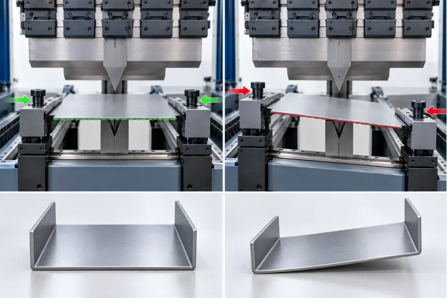
A standard X-axis keeps the backgauge fingers on a common depth reference. Independent X1 and X2 movement allows the two contact points to use different depths.
Conceptually:
X1 = X2 → reference line parallel to the bend line
X1 ≠ X2 → angled reference line
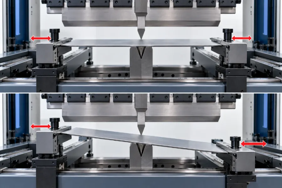
This can provide a suitable gauging reference for tapered parts, angled edges, and other geometries that cannot be positioned effectively against a conventional straight reference plane.
Advanced backgauges may also provide independent R1/R2 movement. Axis names and combinations vary among manufacturers, so the actual movement of each axis matters more than the advertised axis count.
Types of Press Brake Backgauges
Backgauges can also be classified by how their positions are adjusted and controlled.
Manual Backgauge
A manual backgauge uses a handwheel, screw mechanism, scale, or similar system to adjust the stop position.
Its simple design can be sufficient for occasional production and straightforward bends. The limitation becomes more apparent when a job requires frequent dimension changes or multiple gauging positions because each change requires additional manual setup.
Motorized Backgauge
A motorized backgauge uses an electric drive instead of relying entirely on manual adjustment. Depending on the machine design, it may include powered positioning and a digital readout.
Motorized movement alone does not necessarily provide the programmable, multi-step positioning of a CNC backgauge.
CNC Backgauge
A CNC backgauge integrates positioning with the press brake program. Each bending step can use different gauge coordinates, allowing the system to reposition automatically during a multi-bend sequence.
Depending on the configuration, the program may coordinate X, R, Z, independent axes, and retract movements.
Common Backgauge Axis Configurations
Axis combinations are not completely standardized among press brake manufacturers. The following are common examples rather than universal definitions.
| Configuration | Example Axis Arrangement | General Capability |
|---|---|---|
| 2-axis | X, R | Depth and vertical positioning |
| 4-axis | X, R, Z1, Z2 | Adds programmable lateral finger positioning |
| 5-axis | X, R, Z1, Z2, X′ or equivalent | Adds another independent positioning function |
| 6-axis | X1, X2, R1, R2, Z1, Z2 | Greater independent positioning on both sides |
Axis count mainly changes positioning freedom, geometry capability, and automation. A properly configured two-axis backgauge can still be appropriate when the workpiece does not require independent lateral or angled positioning.
How Many Backgauge Axes Do You Need?
Start with the workpiece and bending sequence rather than selecting the highest available axis count.
| Part or Production Requirement | Capability to Consider |
|---|---|
| Parallel reference edges and standard flanges | X and R positioning |
| Formed flanges requiring vertical clearance | Programmable R movement |
| Frequent changes in finger locations | Z1/Z2 positioning |
| Multiple stations along the tooling | Programmable lateral positioning |
| Angled or tapered reference edges | Independent X1/X2 positioning |
| References requiring different heights | Independent R movement |
| Frequent product changeovers | Programmable multi-axis positioning |
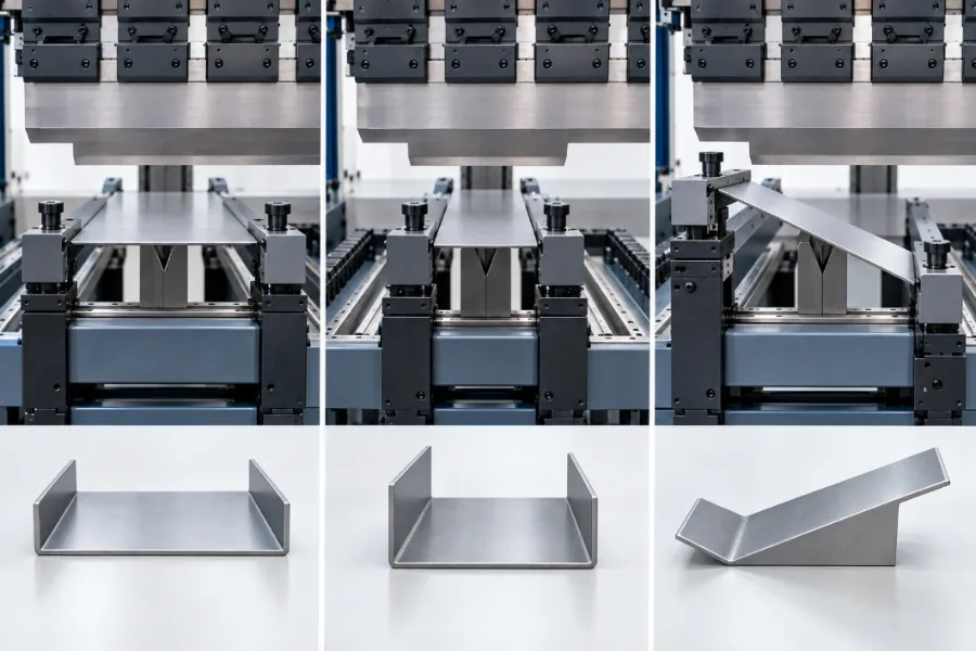
Production mix also affects the decision. A shop producing one stable part in large batches may place more value on repeatability and positioning speed, while high-mix production can benefit more from automatic repositioning and shorter setup changes.
The practical selection chain is:
Part geometry → Bend sequence → Required positioning movements → Backgauge axes
If a part never requires independent depth positioning, adding X1/X2 may increase machine cost and programming complexity without adding useful capability.
What Affects Backgauge Positioning Accuracy?
A programmed coordinate only produces the intended result when the mechanical system reaches that position consistently and the workpiece contacts the intended reference correctly.
Backlash and Mechanical Movement
Backlash is lost motion within a mechanical transmission. Clearance in a ball screw or related components can cause a difference between commanded movement and actual finger movement, particularly when the direction of travel changes.
Repeatability can be checked by moving away from a reference point and approaching the same coordinate multiple times. Direction-dependent variation can indicate backlash or another mechanical issue.
Finger Alignment
When two fingers are intended to share the same X reference, they should establish a consistent plane relative to the bend line.
If one finger sits farther forward than the other, a wide sheet may contact one side first. The resulting flange can taper even though the programmed coordinate appears correct.
Workpiece Contact
Backgauge accuracy cannot compensate for an unstable reference edge.
Long or thin sheets can sag, burrs or irregular cut edges can create false contact points, and inconsistent operator positioning can prevent the workpiece from seating against both fingers. Each can create dimensional variation even when the backgauge reaches its commanded position.
Backgauge Error or Bending Error?
An incorrect flange dimension should not automatically be corrected by changing the X-axis offset. First determine whether the error originates from positioning or from the bending process.
| Symptom | Areas to Check |
|---|---|
| Flange consistently too long or short | X position, programmed dimension, bend calculation, calibration |
| Left and right flange lengths differ | Finger alignment, workpiece seating, reference edge |
| Dimensions vary between identical parts | Backlash, loose components, workpiece positioning, material variation |
| Flange dimension is stable but angle varies | Material, tooling, springback, bending parameters |
| First bend is correct but later bends drift | Gauging reference, bend sequence, interference, retract settings |
Material thickness variation and tooling wear can change the finished result without an actual backgauge positioning error. Applying an X-axis correction before identifying the source can compensate for the symptom while leaving the underlying process problem unchanged.
A useful diagnostic sequence is:
Commanded position → Actual finger position → Repeatability → Left/right alignment → Workpiece contact → Test bend
Choosing the Right Backgauge for a Press Brake
Backgauge configuration should be evaluated together with part geometry, tooling, CNC control, and production requirements.
Key inputs include the reference edges on the part, bend sequence, required tolerances, vertical clearance, frequency of finger repositioning, batch size, product changeovers, positioning speed, repeatability, and automation requirements.
The objective is not to maximize axis count. It is to provide the movements required to position the actual workpiece efficiently and repeatably.
When evaluating a press brake configuration with BENDORA, providing the material, thickness, bending length, part drawing, required tolerance, bend sequence, and production volume gives the engineering team a clearer basis for determining an appropriate machine and backgauge configuration.
Conclusion
A press brake backgauge establishes the reference used to position the workpiece before each bend. X controls depth, R controls vertical position, Z1/Z2 control lateral finger locations, and independent axes such as X1/X2 provide additional positioning freedom for angled or non-parallel references.
The appropriate configuration depends on part geometry and bend sequence rather than axis count alone. Standard parts may require only basic positioning movements, while complex reference edges, frequent changeovers, and multi-step bending can justify additional programmable axes.
FAQ
What does the X-axis do on a press brake backgauge?
The X-axis moves the backgauge front to back, perpendicular to the bend line. It controls gauging depth and is closely related to the flange dimension being produced.
Is a 4-axis backgauge better than a 2-axis backgauge?
Not necessarily. A four-axis configuration such as X, R, Z1, and Z2 adds programmable lateral finger positioning. If the parts do not require frequent lateral repositioning, a properly configured two-axis system may already provide the required capability.
Why does a press brake backgauge retract during bending?
The workpiece rotates as it bends and may move toward the backgauge. When retract is programmed, the gauge moves away at the appropriate stage of the bending cycle to provide clearance and reduce interference with the forming part.
How accurate should a press brake backgauge be?
There is no single accuracy requirement for every application. Compare the specified positioning accuracy and repeatability with the part tolerance, geometry, gauging method, and complete bending process rather than judging accuracy by axis count alone.