PRESS BRAKE MACHINES

CNC Hydraulic Press Brake

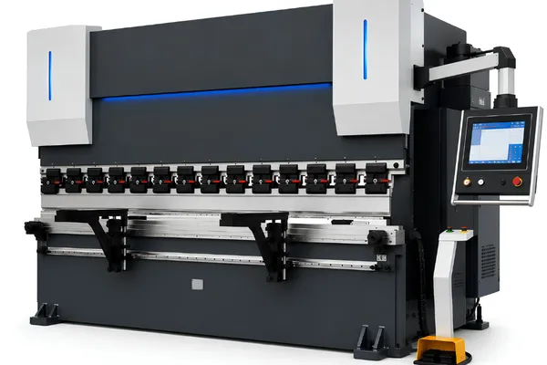
BENDORA provides CNC hydraulic press brake configurations for precision sheet metal bending, combining hydraulic ram control, CNC positioning, backgauge control, and press brake tooling for different fabrication requirements.

Available configurations can be selected around required tonnage, working length, material thickness, part geometry, tooling, and production requirements.

CNC Hydraulic Press Brake Models

Compare CNC hydraulic press brake configurations by bending force and working length. Machine selection should also consider material, thickness, tooling, part geometry, and required positioning capability.

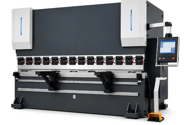
BH-11032 CNC hydraulic press brake with 110-ton bending force and 3,200 mm working length

General Fabrication

For common sheet metal parts requiring a practical balance of bending capacity, working length, CNC positioning, and tooling flexibility.

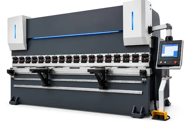
BH-17032 CNC hydraulic press brake with 170-ton bending force and 3,200 mm working length

Medium-Duty Bending

For thicker materials or larger workpieces where higher bending force, appropriate tooling, and stable positioning are required.

BH-22040 CNC hydraulic press brake with 220-ton bending force and 4,000 mm working length

Long & Heavy Bending

For applications involving longer bend lengths, heavier plate, or higher forming forces. Machine capacity should be selected from the actual material and tooling conditions.

Contact Us

Please enable JavaScript in your browser to complete this form.

How to Choose the Right Press Brake Configuration

CNC hydraulic press brake performance depends on more than nominal tonnage. The machine, tooling, positioning system, material, and bending process need to work together for the parts being produced.

Built Around the Press Brake Manufacturing Process

Press brake production involves multiple stages, from structural fabrication and precision machining to machine assembly, system integration and final setup. Each stage can affect machine rigidity, alignment and bending performance.

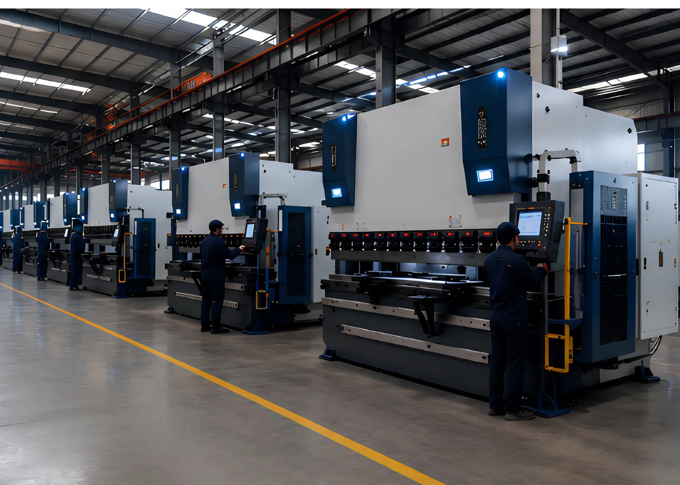
CNC press brake manufacturing line with operators assembling and testing machines in a modern factory

Frame Fabrication
The machine frame provides the structural foundation for bending under load. Frame design, fabrication and preparation should support rigidity and stable machine geometry.

Precision Machining
Critical mounting and alignment surfaces require controlled machining to support accurate assembly of the ram, table, backgauge and related components.

Machine Assembly
Hydraulic systems, CNC controls, backgauges, tooling interfaces and other machine components are integrated according to the required configuration.

Final Setup
Machine functions, positioning and bending setup should be checked before the press brake enters production.

What Should Be Checked Before a Press Brake Enters Production?

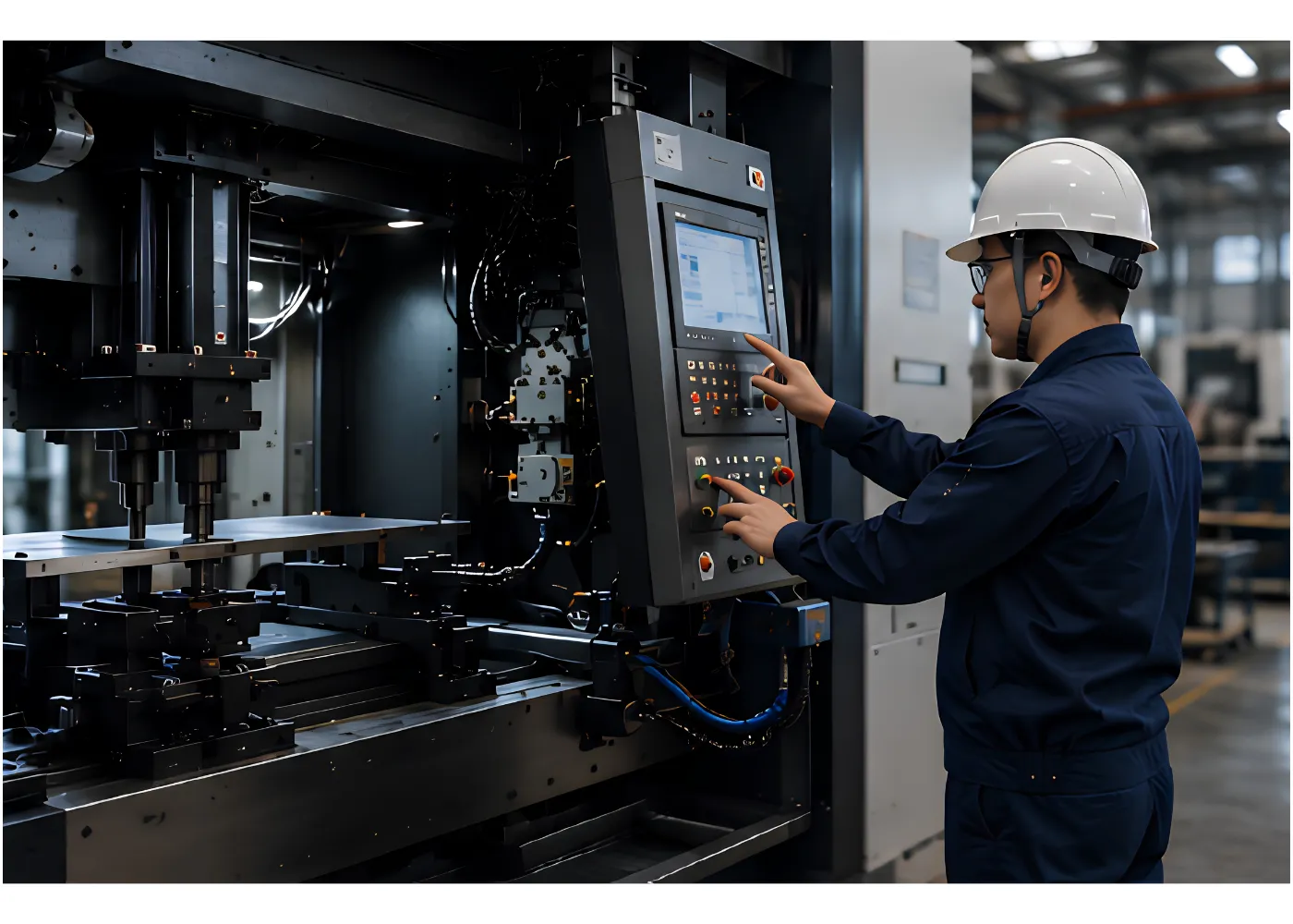
A CNC hydraulic press brake should be evaluated as a complete bending system. Machine geometry, ram movement, backgauge positioning, CNC functions and trial bending all influence the final bending result.

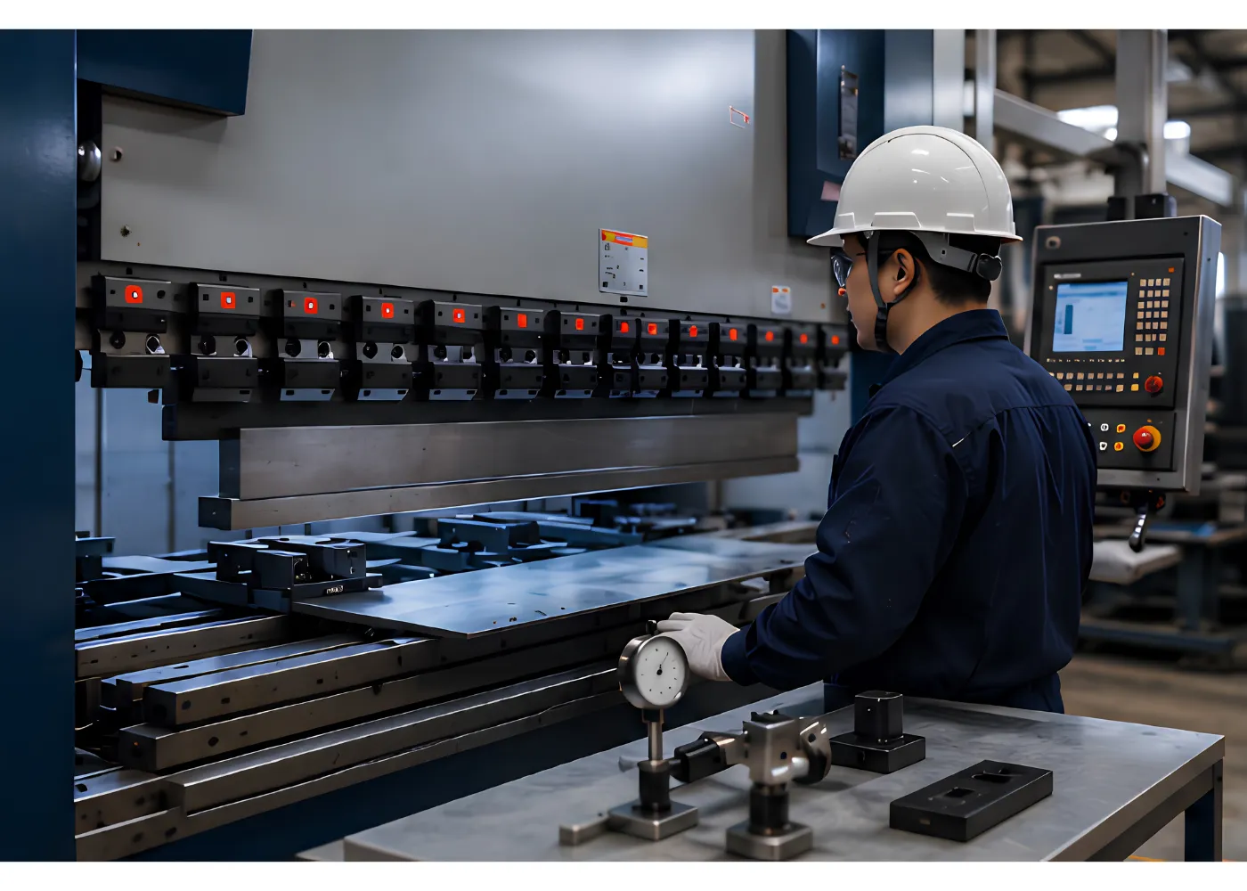
CNC hydraulic press brake quality inspection and precision testing before machine delivery

Functional Inspection
Hydraulic operation, CNC functions, backgauge movement and relevant machine functions should be checked under operating conditions.

Machine Geometry & Positioning Checks
Ram movement, machine alignment and backgauge positioning should be checked because deviations can contribute to inconsistent bending results.

Safety Function Checks
Installed guarding and safety devices should be checked according to the machine configuration and intended operating conditions.

Trial Bending Verification
Trial bends provide a practical way to evaluate machine setup, tooling, positioning and bending performance before production.

Configure the Press Brake Around Your Bending Requirements

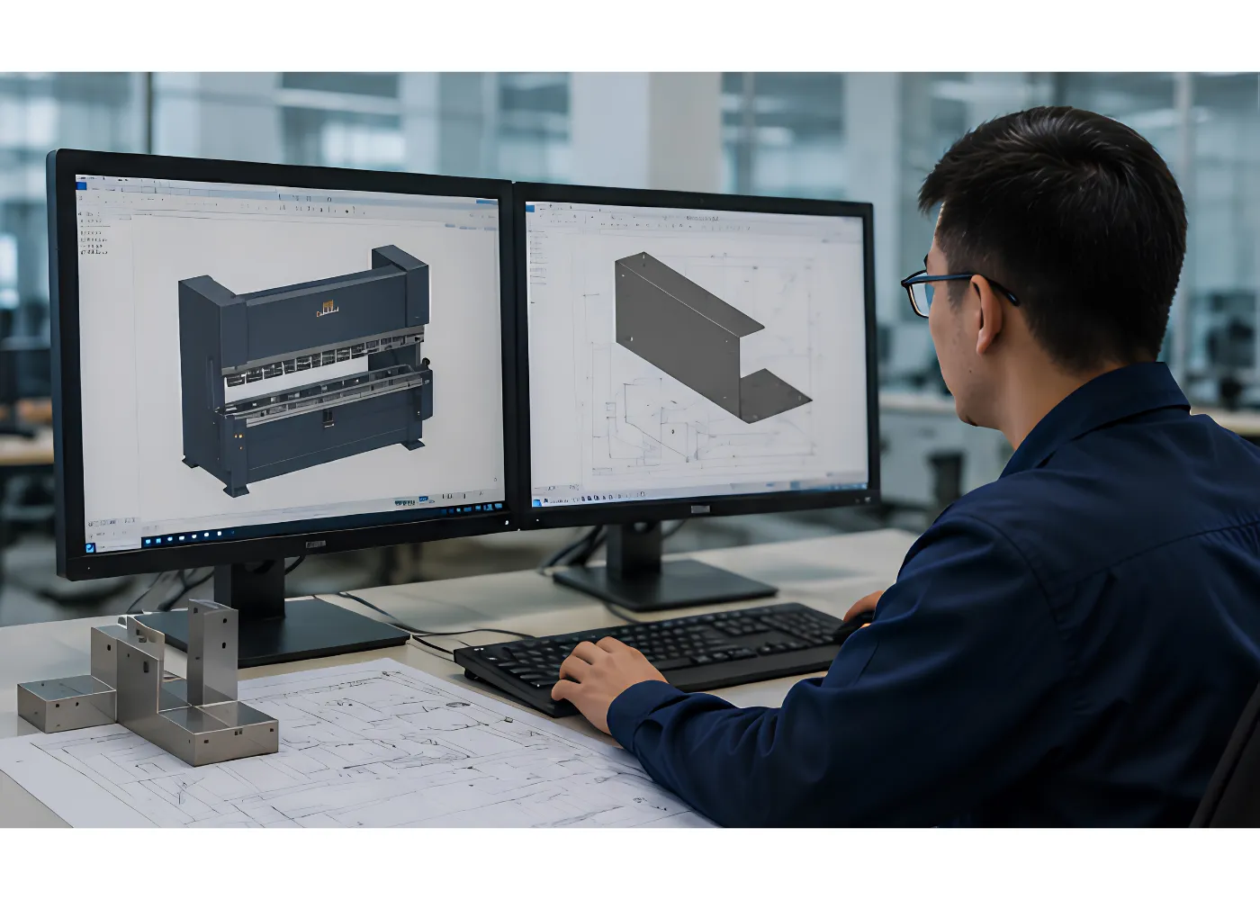
Press brake selection should start with the workpiece rather than a predetermined machine specification. Material, thickness, bending length, part geometry and tooling requirements determine the machine capacity and configuration needed for the application.

Press brake engineering design for custom sheet metal bending requirements and machine configuration

Application-Based Machine Selection
Material strength, sheet thickness, bending length, part geometry and required bend radius provide the basis for selecting machine capacity.

CNC & Backgauge Configuration
CNC control and backgauge axes should be selected according to bend sequence, positioning requirements and part complexity.

Tooling & Bend Geometry
Punches, dies and V-die openings should be matched to material thickness, bend radius, flange dimensions and the selected bending method.

Automation Requirements
Material handling, robotic bending and other automation options can be considered where production volume, part size or process requirements justify them.

Plan for Setup, Operation and Maintenance

Press brake requirements continue beyond initial machine selection. Installation conditions, operator setup, routine maintenance and replacement-part planning should be considered when evaluating a machine for long-term production.

Press brake technical support and maintenance with CNC system diagnostics for reliable machine operation

Installation & Setup
Machine foundation, leveling, electrical and hydraulic requirements, tooling setup and initial machine configuration should be considered before production begins.

Operation & Troubleshooting
Operators need clear information for CNC setup, tooling changes, bending adjustments and identifying common machine or process-related problems.

Routine Maintenance
Hydraulic systems, tooling, backgauges, lubrication points and other machine components require appropriate inspection and maintenance according to operating conditions.

Spare Parts Planning
Wear components and critical replacement parts should be identified according to the machine configuration and expected production environment.

How to Choose a CNC Hydraulic Press Brake

Choosing a CNC hydraulic press brake starts with the parts you need to bend rather than a predetermined machine tonnage.

A practical selection sequence is:

Material → Thickness → Part Geometry → Bending Length → V-Die & Tooling → Required Force → Machine Configuration

Evaluating the application in this order helps avoid selecting a machine based on tonnage alone.

How Much Press Brake Tonnage Do You Need?

Required bending force depends on several variables working together:

  • Material type and strength
  • Sheet thickness
  • Bending length
  • V-die opening
  • Bending method
  • Bend geometry
  • Required bend radius

Increasing material thickness can significantly increase the required force, while a wider V-die opening generally reduces the bending force required for air bending.

Use the dedicated calculator to estimate machine capacity from the main bending variables.

Use the Press Brake Tonnage Calculator →

Learn How Press Brake Tonnage Is Calculated →

Working Length Matters as Much as Tonnage

Bending force and working length describe different machine requirements.

Tonnage determines the available forming force, while working length determines the width of the workpiece the machine can accommodate.

A press brake can provide sufficient bending force and still be unsuitable if the required part exceeds its usable working length. Both parameters should therefore be evaluated independently during machine selection.

How V-Die Selection Affects Bending

The V-die opening affects several important bending conditions:

  • Required bending force
  • Inside bend radius
  • Minimum flange dimensions
  • Material deformation
  • Tool-to-material contact
  • Finished part geometry

A wider V opening generally reduces required bending force but also changes the bend geometry produced during air bending.

The appropriate die should therefore be selected around material thickness, bend radius, flange dimensions, forming method, and part geometry.

Learn How to Choose a Press Brake V Opening →

Air Bending vs. Bottom Bending vs. Coining

Different bending methods change the relationship between tooling contact, forming force, angle control, and flexibility.

Air Bending

Air bending forms the sheet through controlled punch penetration without forcing the workpiece completely into the die profile.

It provides flexibility for producing different bend angles with the same tooling, although material properties and springback influence the final angle.

Bottom Bending

Bottom bending brings the workpiece into closer contact with the punch and die geometry.

Tooling geometry and material behavior still need to be considered when establishing the final bending condition.

Coining

Coining uses substantially greater forming pressure to plastically deform the material more aggressively in the bend area.

The higher force requirement makes machine capacity and tooling selection particularly important.

What Affects Press Brake Bending Accuracy?

Bending accuracy depends on the complete bending system rather than CNC positioning alone.

Machine Structure + Positioning + Tooling + Material + Bending Process = Bending Result

Material variation, springback, tooling condition, machine deflection, ram control, backgauge positioning, and setup can all affect the final bend angle.

Crowning can be used to compensate for machine deflection across longer bending lengths, while process adjustments may be required to account for material and springback variation.

Learn About Press Brake Crowning →

Why Is My Press Brake Bending Angle Inconsistent? →

Press Brake Tooling and Die Selection

Press brake tooling is part of the bending system rather than simply an accessory attached to the machine.

Punch and die geometry can influence:

  • Bend angle
  • Bend radius
  • Required force
  • Flange geometry
  • Part clearance
  • Surface condition
  • Setup efficiency

Tooling should be selected around the part geometry, material, bending method, and production requirements.

Explore Press Brake Tooling Types →

Learn How to Choose Press Brake Tooling →

When Specialized Tooling May Be Required

Special tooling may be useful for applications involving:

  • Hemming
  • Step or Z bending
  • Small flanges
  • Complex profiles
  • Surface-sensitive materials
  • Frequent tooling changes

Part geometry and bending sequence should also be checked for interference between the workpiece, punch, die, and previously formed bends.

Common Press Brake Bending Problems

Machine capacity alone does not determine whether a part can be bent consistently. Material behavior, tooling, setup, and bend sequence can introduce production problems even when the machine has sufficient tonnage.

Surface Scratches

Sliding contact between the sheet and die can leave visible marks. Tooling condition, die geometry, surface protection, and the material finish should be considered when appearance is important.

Cracking at the Bend

Cracking can be influenced by material ductility, rolling direction, edge condition, thickness, and inside bend radius.

Inconsistent Bend Angles

Springback, material variation, tooling condition, machine deflection, positioning, and process setup can all contribute to angle variation.

Learn About Common Press Brake Bending Problems →

Part or Tool Interference

Complex profiles may interfere with the punch, die, machine, or sections formed during earlier bending operations.

Part geometry and bend sequence should therefore be reviewed before the tooling and machine configuration are finalized.

CNC Hydraulic Press Brake Selection Checklist

Before selecting a machine or preparing a quotation, define the main variables of the bending application:

  • Material type
  • Material thickness
  • Maximum bending length
  • Part dimensions
  • Bend angles
  • Required bend radius
  • Production volume
  • Number and sequence of bends
  • Surface-finish requirements
  • Part drawing, if available
  • Special tooling requirements

Starting with this information provides a better basis for evaluating bending force, working length, tooling, backgauge requirements, and the overall CNC hydraulic press brake configuration.

FAQ
How do I choose the right CNC hydraulic press brake?

Start with material type, thickness, maximum bending length, part geometry, bend radius, and production requirements. These variables help determine the required tonnage, working length, tooling, backgauge, and CNC configuration.

Required tonnage depends on material strength, thickness, bending length, V-die opening, and forming method. A calculation provides an initial capacity estimate, but tooling and the complete bending application should also be considered.

Bending force describes the forming capacity available to deform the material. Bending length describes the available working width for the workpiece. A suitable press brake needs to satisfy both requirements.

V-die opening influences required bending force, inside bend radius, flange dimensions, and material deformation. The appropriate opening depends on material thickness, tooling, forming method, and required part geometry.

Yes, but required machine capacity and tooling vary with material strength, thickness, bend length, bend radius, and the selected forming method.

Find the Right CNC Hydraulic Press Brake

Share your material, thickness, bending length, part geometry, and production requirements to identify the machine capacity, tooling, and CNC configuration required for your application.