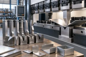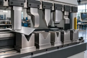
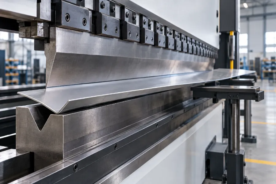
An inconsistent press brake bending angle does not always mean the machine is inaccurate. The final angle depends on material behavior, tooling geometry, punch penetration, machine deflection, springback, and the forming method.
The fastest way to find the cause is to identify the pattern of the angle error before changing CNC correction or crowning. A bend that is uniformly 2° open requires a different diagnosis from one that is correct at both ends but open in the center.
Quick Diagnosis: What Does Your Bend Angle Error Look Like?
Before changing the program, make a representative test bend and measure the included angle at the left, center, and right. If the problem varies between parts, measure several consecutive pieces using the same measurement method and record the results.
| What You Observe | Check First | Likely Problem Area | Do Not Adjust First |
|---|---|---|---|
| Entire bend is consistently too open or closed | Material, springback, ram depth | Material / process | Crowning |
| Center differs from both ends | Left-center-right angle distribution | Deflection / crowning | Global angle correction |
| Left and right angles differ | Tool seating, alignment, ram parallelism | Machine / tooling | Backgauge correction |
| Angle changes randomly from part to part | Measurement, thickness, material batch, tooling stability | Material / setup | Y1/Y2 correction |
| Angle gradually drifts during production | Temperature, hydraulics, mechanical stability | Machine stability | Static angle offset |
| Local error appears near one tooling section | Tool wear, seating, segment alignment | Tooling | Global CNC correction |
| Angle is correct but flange length changes | Backgauge and reference position | Positioning | Ram depth |
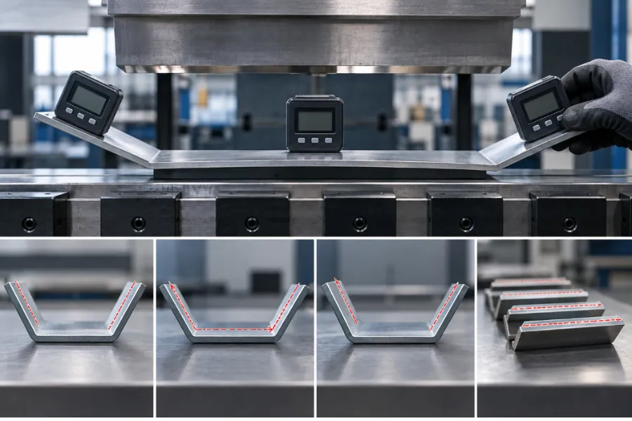
The key is to separate a uniform error from a distributed error, and a random variation from a progressive drift. These patterns point toward different physical causes and should not be corrected with the same machine parameter.
Why Can the Same Press Brake Program Produce Different Angles?
A CNC program controls machine movement, but it cannot make every physical variable identical.
In air bending, the final angle is controlled primarily by punch penetration into the die opening. However, material properties, actual thickness, tooling geometry, V-opening, machine behavior, and springback determine the angle actually produced at a given penetration.
A useful way to understand the process is:
Material behavior + tooling geometry + punch penetration + machine behavior + springback = final bend angle
This explains why two sheets with the same nominal grade and thickness can produce different results under the same program.
Angle correction should compensate for a verified, repeatable process offset. It should not be used to hide an unidentified material or mechanical variable that is still changing.
1. The Entire Bend Is Consistently Too Open or Too Closed
When approximately the same angle error appears across the full bend length, start with variables that affect the entire bend rather than crowning.
Springback Has Changed
Springback occurs when the material elastically recovers after bending force is removed. The included angle typically opens by some amount after unloading.
The amount depends on factors such as:
- Material mechanical properties
- Actual sheet thickness
- Bend radius relative to thickness
- V-opening and tooling geometry
- Forming method
- Final bending condition
Under comparable bending conditions, materials with higher yield strength relative to elastic modulus generally require greater springback compensation. Stainless steel commonly shows more springback than mild or cold-rolled steel in comparable sheet-metal bending applications, but the actual recovery depends on the specific grade, condition, thickness, bend radius, tooling, and forming method.
A correction that produced 90° on one material batch therefore may not produce exactly the same angle after the material changes.
Actual Material Thickness or Properties Have Changed
Nominal thickness is not necessarily actual thickness. Material can remain within its specified tolerance while still varying enough to affect precision air bending.
Before changing machine compensation, verify:
- Actual thickness at representative locations
- Material grade and condition
- Material batch or heat
- Supplier changes
- Blank orientation where grain direction is relevant
Different batches of the same nominal material can also have different mechanical properties and springback behavior.
Grain orientation can affect forming behavior and elastic recovery. If orientation has a measurable effect on the part, keep it consistent rather than assuming one grain-direction rule applies to every alloy and temper.
Ram Depth or Angle Correction Is Incorrect
If several test pieces show approximately the same angle error across the entire bend length, the programmed penetration or angle correction may need adjustment.
Make a controlled trial bend, measure the actual angle, apply the appropriate depth or angle correction, and verify the result again.
Do not use crowning to solve a uniform global angle offset. Crowning changes compensation along the bending length rather than correcting the entire bend by the same amount.
2. The Center Angle Differs From Both Ends
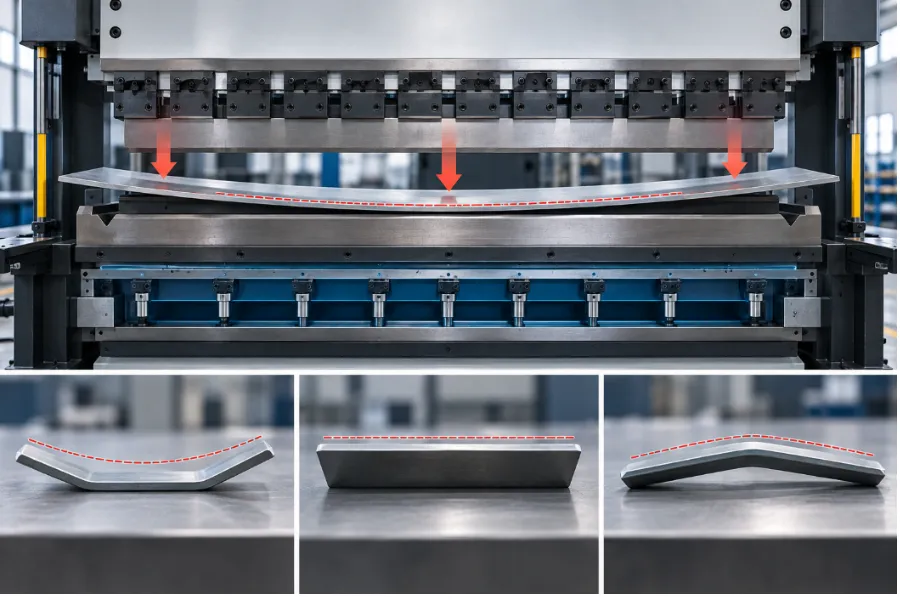
A different pattern appears when a long workpiece shows a repeatable angle difference between the center and ends.
This is a reason to investigate load-induced machine deflection and crowning rather than simply adding more global angle correction.
Why Press Brakes Deflect Under Load
A press brake is not infinitely rigid. Bending force produces elastic deformation in the ram, bed, and supporting structure.
If this deformation changes effective punch penetration along the working length, different sections of the workpiece receive different forming conditions. The result is a systematic angle variation along the bend.
This center-to-end variation is sometimes described as the “canoe effect” in press brake bending. The term describes the angle distribution; it is not a separate failure mechanism.
How to Confirm a Deflection Problem
Make a representative long test bend and measure:
- Left
- Center
- Right
Use the same measurement locations and method for every test.
If the same center-to-end pattern repeats and remains at the same position on the machine, machine deflection or its compensation becomes a strong suspect.
For an additional isolation test, repeat the same setup at another position along the machine bed, or use another blank from the same material batch while keeping the process variables unchanged. If the error remains tied to the machine position, investigate the machine and tooling. If it follows the material or blank, investigate material or setup variables.
When Crowning Is the Right Direction
Crowning compensates for the deflection profile that develops under bending load. Depending on machine configuration, compensation may be mechanical, hydraulic, or CNC controlled.
Consider adjusting crowning when:
- A repeatable center-to-end angle difference exists.
- The error remains associated with machine position.
- The problem becomes more apparent on longer or more heavily loaded bends.
- Material and tooling variables have been reasonably isolated.
Do not start with crowning when the entire bend is uniformly off target, the result changes randomly between sheets, tooling is worn or misaligned, or the main error is left-to-right.
Crowning corrects deflection, not every bending-angle error.
3. The Left and Right Bend Angles Are Different
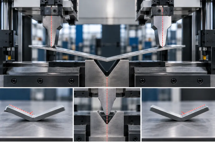
A left-right difference indicates that the two sides of the workpiece may not be receiving the same effective punch penetration.
The cause can be machine synchronization, but simpler mechanical conditions should be eliminated first.
Check Tooling Alignment and Seating
A punch that is not centered over the V-die can create asymmetric loading. Tooling that is not fully seated can produce a similar result.
Inspect:
- Punch and die centerline alignment
- Tool seating
- Clamping surfaces
- Dirt, scale, or debris at contact surfaces
- Segmented-tool joints
- Lower-die stability
Correct mechanical alignment before using CNC compensation to mask the error.
Check Ram-to-Worktable Parallelism
The ram and worktable must maintain the required relationship during bending.
Machine level, mechanical wear, calibration, guide condition, or structural changes can produce a side-to-side penetration difference. If controlled trial bends repeatedly show the same left-right pattern, parallelism should be checked.
Check Y1/Y2 Synchronization
On many electro-hydraulic synchronized press brakes, Y1 and Y2 represent independently monitored or controlled ram positions on the left and right sides.
A synchronization or calibration problem can allow one side to penetrate farther than the other. However, Y1/Y2 should not become the default adjustment whenever a left-right angle difference appears.
A useful diagnostic order is:
Tool seating and alignment → machine level and parallelism → Y1/Y2 synchronization or calibration
This reduces the risk of compensating electronically for an unresolved mechanical problem.
4. Bend Angle Changes From Part to Part
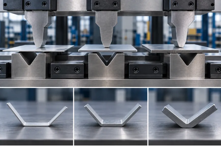
If the same program produces different angles on consecutive parts without a clear directional trend, investigate variables that can change between workpieces.
Confirm the Measurement First
Before changing the press brake, confirm that the angle measurement itself is repeatable.
Measure the same unloaded part several times using the same contact points, support method, and reference location. If the reading changes materially, resolve the measurement method before diagnosing the machine or material.
Measure Actual Material Thickness
Do not rely only on nominal thickness.
Measure representative locations and compare multiple blanks. In air bending, thickness variation changes the relationship between punch penetration, tooling, and final formed geometry.
Check Material Batch and Mechanical Properties
Two batches sold under the same material designation do not necessarily behave identically during bending.
Differences in strength, hardness, material condition, or processing history can change springback. A trial bend from the actual production batch is therefore more useful than assuming an old correction remains valid indefinitely.
Keep Blank Orientation Consistent
Changing the relationship between the bend line and rolling direction can change forming behavior.
If orientation has a measurable effect on the part, record it with the production setup, particularly when nesting or material batches change.
Verify Tooling Setup Stability
Random variation can also indicate an unstable setup.
Check for:
- Loose clamps
- Incomplete tool seating
- Contaminated clamping surfaces
- Multi-V die movement
- Height differences or gaps between tooling segments
A fixed CNC offset cannot reliably correct a mechanical condition that moves from one stroke to the next.
5. Bend Angle Gradually Drifts During Production
Random variation and progressive drift should not be diagnosed as the same problem.
If early parts are acceptable but the angle gradually changes during a production run, record the results in sequence and look for a time-dependent condition.
Hydraulic and Thermal Conditions
On hydraulic press brakes, oil temperature changes during operation. Temperature affects fluid viscosity and can influence hydraulic system response.
If angle drift correlates with machine operating time, inspect hydraulic condition, temperature stability, and the machine manufacturer’s operating requirements rather than repeatedly changing the angle correction.
Avoid assuming a universal warm-up time. Required stabilization depends on the machine, hydraulic system, oil specification, ambient conditions, and operating cycle.
Progressive Mechanical Movement
A directional change can also indicate that something is moving, loosening, or wearing during production.
Inspect:
- Tool clamping
- Tooling movement
- Mechanical backlash
- Guide condition
- Hydraulic stability
- Axis calibration
- Progressive tool wear
A static correction can compensate for a static offset. It cannot permanently correct a variable that continues to change.
6. Tooling Problems That Are Easy to Misdiagnose
Tooling wear develops gradually, so operators may compensate through CNC corrections without realizing that the original physical geometry has changed.
Worn Punch Tips
Repeated bending can change the punch tip radius through wear, rounding, or localized damage.
The controller may still contain the original tooling geometry even though the physical tool no longer matches that data. This changes the relationship between programmed penetration and actual forming behavior.
Worn Die Shoulders
Die shoulders are critical contact areas during bending.
As they wear, the material contacts and moves over a different surface geometry. This can affect material flow, bend geometry, and angle repeatability.
If an established job gradually requires more correction, compare the production tooling with a known-good tool before treating the change as a permanent machine offset.
Segmented and Multi-V Tooling
Segmented tooling introduces additional interfaces. Check that sections are fully seated, aligned, and free from height differences or gaps that disturb the bend.
With multi-V dies, also verify the selected groove position and die centerline. A shifted die block can change the load path even when the nominal V-opening is correct.
7. Does the Bending Method Affect Angle Consistency?
Yes. The forming method changes how the final angle is established and therefore changes the troubleshooting logic.
| Bending Method | How the Angle Is Formed | Sensitivity to Variation | Main Trade-Off |
|---|---|---|---|
| Air bending | Controlled primarily by punch penetration | More sensitive to material and springback variation | Flexible angle control with relatively low force |
| Bottoming | Material conforms more closely to punch and die geometry | Can reduce some angle variation but still requires springback control | Less flexible and more tooling-dependent |
| Coining | High pressure plastically sets the bend region | Springback is substantially reduced | Much higher forming force and tooling load |
Air bending exposes material and springback variation more clearly because the final angle depends strongly on penetration. Bottoming and coining constrain the material more strongly through tooling geometry and force, but introduce different tooling and tonnage requirements.
Changing forming methods therefore changes both the resulting bend geometry and the appropriate correction strategy.
8. How V-Die Selection Affects Angle Stability
The V-opening influences bending force, inside radius, material contact, and springback behavior.
Changing the V-die can therefore invalidate an angle correction established with a previous tooling setup, even when the material and target angle remain unchanged.
Rules such as selecting a V-opening as a multiple of material thickness are useful starting points for many air-bending applications, but they are not universal formulas. The appropriate opening depends on material, thickness, required inside radius, part geometry, tooling capacity, and the bending requirement.
For detailed V-die selection, evaluate the opening as part of the complete material-and-tooling combination rather than changing it simply to force the angle closer to target.
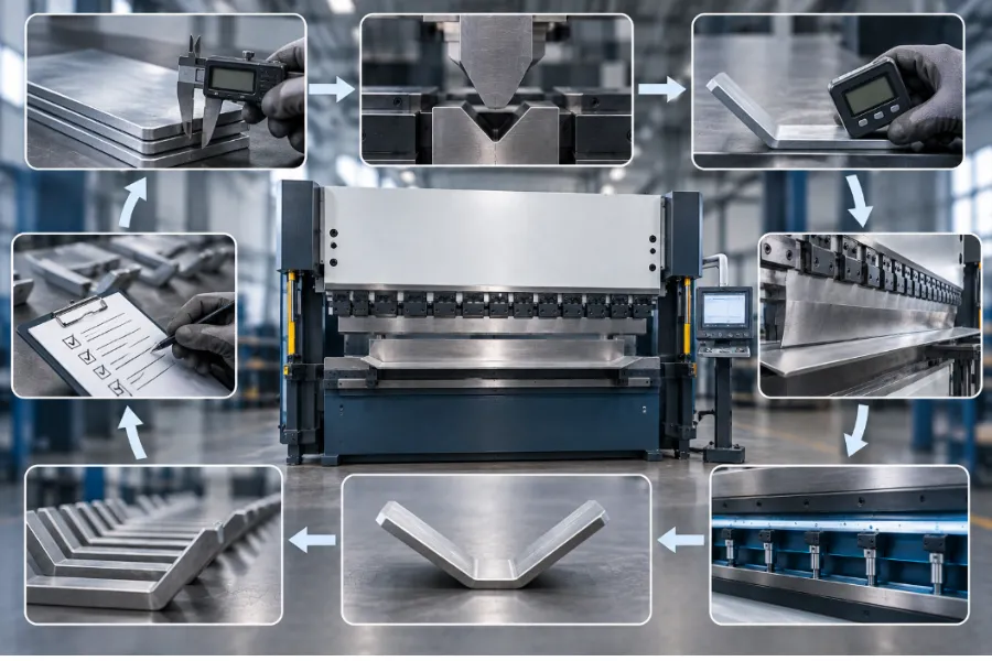
9. A Step-by-Step Press Brake Angle Troubleshooting Procedure
Changing several parameters at once makes troubleshooting slower because it becomes difficult to identify which adjustment affected the result.
Use a controlled process instead.
Step 1: Measure the Error Pattern
For a long workpiece, measure the left, center, and right using consistent measurement locations and method.
For part-to-part variation, measure several consecutive pieces and record them in production order.
Classify the error as:
- Uniform
- Center-to-end
- Left-to-right
- Random between parts
- Progressive over time
Step 2: Confirm the Material
Measure actual thickness and confirm the material grade and batch.
If the problem appeared after a material change, test the new batch before recalibrating the machine.
Step 3: Inspect the Tooling
Check:
- Punch tip condition
- Die shoulders
- Alignment
- Seating
- Clamping
- Segmented-tool joints
Clean the relevant contact surfaces before making machine adjustments.
Step 4: Run a Controlled Trial Bend
Keep the important variables consistent:
- Material
- Tooling
- Program
- Bend length
- Workpiece orientation
- Positioning method
Change one variable at a time.
Step 5: Separate Uniform From Distributed Error
A uniform error points first toward material behavior, springback, tooling data, or punch penetration.
A distributed error along the bend length points toward tooling alignment, machine deflection, crowning, parallelism, or synchronization.
Step 6: Separate Random Variation From Progressive Drift
If the error moves unpredictably between parts, inspect material and setup consistency.
If it changes progressively with production time, investigate thermal, hydraulic, mechanical, or calibration conditions.
Step 7: Apply One Correction and Verify Again
Make one relevant adjustment, produce another test bend, and compare the measurements.
Once the process is stable, record the verified combination of material, actual thickness, tooling, bend length, and angle correction for repeat production.
10. What If the Angle Is Correct but the Flange Dimension Is Wrong?
An accurate angle with an incorrect or changing flange length points toward positioning rather than angle formation.
The backgauge primarily establishes the workpiece position relative to the tooling. Check:
- X-axis position
- Backgauge repeatability
- Gauge finger condition
- Mechanical backlash
- Workpiece seating
- Burrs or irregular reference edges
Backgauge errors can affect the final geometry of multi-bend parts, but they should not automatically be diagnosed as a direct bending-angle problem.
Measure both angle and flange length during troubleshooting. They describe different parts of the bending process.
11. How to Prevent Press Brake Angle Variation in Production
Once a stable bending process has been established, preserve the variables that produced it.
For precision and repeat production:
- Measure actual material when batches change.
- Perform a trial bend before committing production material.
- Record material, tooling, bend length, orientation, and verified correction.
- Monitor tooling wear rather than continually adding CNC compensation.
- Standardize tooling installation and clamping.
- Check left-center-right angle distribution on long bends.
- Maintain machine calibration and hydraulic condition according to manufacturer requirements.
- Keep material correction, global angle correction, and crowning compensation as separate process controls.
For high-volume or tight-tolerance production, in-process angle measurement can reduce dependence on manual first-piece correction when properly integrated with the press brake control system.
For multi-bend parts, inspect intermediate operations when necessary. Small angle and positioning errors can accumulate through successive bends and become more visible during final assembly.
FAQ
Why Does My Press Brake Bend 90° on One Side and 92° on the Other?
A repeatable left-to-right difference suggests unequal effective punch penetration. Check tooling seating and alignment first, then machine level, ram-to-worktable parallelism, and Y1/Y2 synchronization or calibration where applicable.
Why Is the Center of My Bend Different From the Ends?
Long bends can be affected by elastic deformation of the press brake under load. If left-center-right measurements repeatedly show the same center-to-end pattern, inspect tooling condition, machine deflection, and crowning rather than applying only a global angle correction.
Can Material Thickness Change the Press Brake Bend Angle?
Yes. Actual thickness affects the relationship between punch penetration, tooling, and material deformation, particularly during air bending. Measure the production material rather than relying only on nominal thickness when troubleshooting precision bends.
Can Worn Press Brake Tooling Cause Inconsistent Angles?
Yes. Wear at the punch tip or die shoulders changes the physical geometry and contact conditions used to form the bend. The CNC program may remain unchanged even though the tooling no longer matches its original geometry.
Should I Adjust Crowning Every Time the Bending Angle Is Wrong?
No. Crowning is intended primarily to compensate for machine deflection along the bending length. Uniform angle error, material variation, tooling wear, left-right synchronization problems, and positioning errors require different corrections.