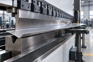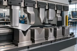
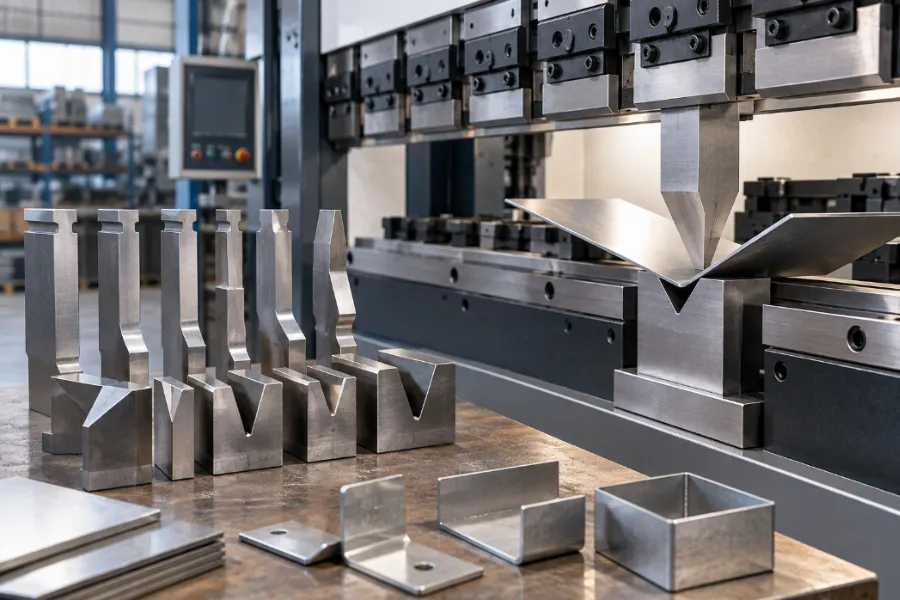
Choosing press brake tooling starts with the part, not the tool rack. Material, thickness, bend length, target angle, inside radius, flange geometry, surface requirements, and production volume all affect the tooling combination.
Different bending jobs can fail for different reasons. A standard bend may be limited by V-opening and bending force, a short flange by die support, a deep box by punch interference, and an appearance-critical part by surface marking.
A practical tooling selection process follows this sequence:
Part requirements → bending method → V-opening → radius → flange → punch geometry → bending force → tooling load → interference → bend sequence
Start With the Part Drawing, Not the Tool Rack
Review the finished drawing and flat pattern before selecting the punch and die. A combination that works for the first bend may become unsuitable after another flange has been formed.
| Job Requirement | Why It Matters |
|---|---|
| Material and grade | Affects tensile strength, springback, cracking risk, and bending force |
| Material thickness | Influences V-opening, radius, and required force |
| Bend length | Affects total force and required tool length |
| Bend angle | Influences overbend clearance and tool angle |
| Inside bend radius | Affects V-opening and punch nose selection |
| Flange length | Can limit the usable V-opening |
| Existing or return flanges | May interfere with the punch body |
| Box dimensions | Affect punch profile, height, and segmentation |
| Holes near the bend | May deform during forming |
| Surface finish | May require mark-reducing tooling |
| Production quantity | Influences standard, modular, or dedicated tooling |
The press brake must also be checked at this stage. Tonnage, working length, stroke, daylight, throat depth, table width, tool holder, and clamping interface can eliminate a tooling combination before production begins.
Step 1: Match the Tooling to the Bending Method
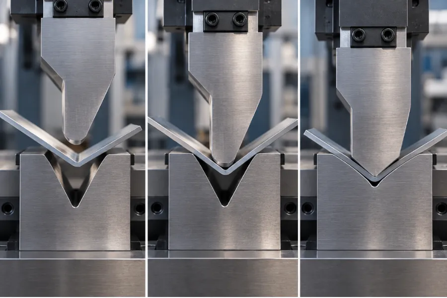
The bending method changes the relationship between tooling geometry, material behavior, and required force.
Air Bending
In air bending, the sheet contacts the punch and two die shoulders without being forced completely into the die. Different angles can therefore be produced with the same basic tooling by changing ram penetration.
Springback must be considered because the material partially recovers after unloading. The V-opening and punch nose also influence the radius that naturally develops during forming.
Bottoming
Bottoming brings the material into closer contact with the punch and die geometry. Tool angle, material thickness, springback, and V-opening therefore have a tighter relationship with the finished bend.
The process also requires substantially more force than air bending, making both machine capacity and tooling load important constraints.
Coining
Coining forces the material closely into the tooling geometry under very high pressure and can significantly reduce springback.
Its force requirement can be many times higher than air bending. It should therefore not be used simply to compensate for an unsuitable air-bending setup by increasing pressure.
Step 2: Establish a Candidate V-Die Opening
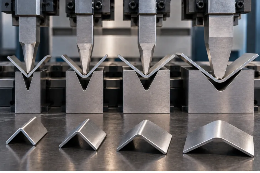
Material thickness is a useful starting point for V-die selection, but it does not determine the final opening by itself.
For many conventional mild-steel bending applications, roughly six to eight times the material thickness can provide an initial range to evaluate. The appropriate ratio can change with bending method, material strength, target radius, flange geometry, and process conditions.
The common 8× thickness rule should therefore be treated as a starting point, not a universal specification.
For each candidate V-opening, check three conditions:
- Does it produce a suitable inside radius?
- Can it support the shortest flange?
- Does it keep the required force within safe limits?
Understand the V-Opening Trade-Off
A wider V-opening generally:
- Reduces required bending force
- Produces a larger naturally formed radius
- Requires a longer flange for proper support
- Can reduce concentrated contact pressure
A narrower V-opening generally:
- Increases required force
- Supports a smaller bend radius
- Can accommodate a shorter flange
- Increases concentrated loading and marking risk
The widest die is therefore not automatically the best die. A wider opening may solve a tonnage problem while creating a radius or flange problem.
Step 3: Verify the Required Inside Bend Radius
After establishing candidate V-openings, compare their expected radius with the drawing.
For some conventional bottom-bending conditions, an inside radius around V/6 can be used as a starting reference. This is an empirical relationship rather than a universal bend-radius formula. Actual results depend on material, thickness, tensile strength, bending method, and tooling geometry.
Air bending requires additional consideration because the sheet develops a natural radius as it spans the die opening. The punch nose does not necessarily define the final inside radius.
The objective is to avoid forcing the material into an unnecessarily sharp radius when the selected V-opening and material would naturally form a larger one. Large-radius parts may require a radius punch or another suitable forming strategy.
Step 4: Check the Minimum Flange
A V-opening can satisfy the radius requirement and still be unsuitable because the flange is too short.
During V-bending, the workpiece must remain adequately supported by the die shoulders. For some V-bending setups, a useful preliminary screening approximation is:
Minimum flange ≈ (V ÷ 2) + punch radius
This is not a universal minimum-flange formula. Actual capability also depends on die shoulder geometry, punch geometry, bend angle, and the specific tooling system. Final selection should be checked against the tooling manufacturer’s data.
The resulting trade-off is:
Wider V → lower force → larger radius → longer minimum flange
If the drawing contains a short flange, geometry may therefore eliminate a wider die before machine tonnage does.
Step 5: Select the Punch Radius, Angle, and Profile
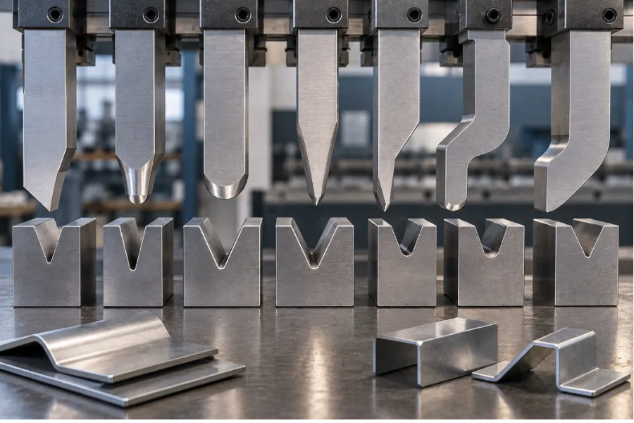
Once the candidate die opening has passed the radius and flange checks, evaluate the upper tool.
Punch Nose Radius
The punch nose should be compatible with the required inside radius, material thickness, material bendability, and selected V-opening.
An unnecessarily small nose concentrates pressure near the bend line and can increase the risk of marking, localized deformation, or cracking. In air bending, the punch radius should be considered together with the radius naturally developed over the die.
Punch Angle
The tooling must provide sufficient angular clearance for springback.
Materials with greater elastic recovery may need to be bent beyond the final target angle. Punch and die angles should therefore be selected according to the actual forming condition rather than assuming that a 90-degree finished part always requires 90-degree tooling.
Punch Profile
Punch profile becomes critical when previously formed geometry creates an interference risk.
A straight punch works for open bends where the part remains clear of the tool body. A gooseneck or relieved profile may be required for return flanges, box walls, or other features that would collide with a straight punch.
Step 6: Check Part Geometry and Tool Interference
Correct radius and angle do not guarantee that a tool can manufacture the complete part.
Check the workpiece against:
- Return flanges
- Box walls
- Deep channels
- Adjacent bends
- Internal bends
- Hardware and protruding features
- Backgauge contact surfaces
- Ram and bed clearance
For box bending, segmented tooling can provide side clearance where a continuous tool would interfere with an existing wall. A relieved punch can provide additional vertical clearance.
Tool height also matters. Punches, dies, holders, and extensions consume available daylight, so the complete setup must fit within the machine’s available space.
Collision checking should cover the complete operation:
Load → gauge → bend → retract → rotate → next bend → remove
A tool that can form the bend but prevents the finished part from being removed is not a workable tooling choice.
Step 7: Verify Bending Force and Tool Load Capacity
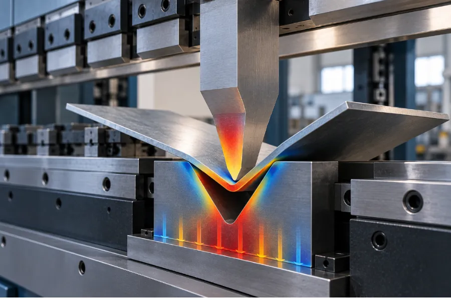
After the geometry has been checked, verify the required load.
For conventional V-bending, the approximate force relationship can be expressed as:
P ∝ L × t² × σ / V
Where:
- P = required bending force
- L = bend length
- t = material thickness
- σ = material tensile strength
- V = V-die opening
This relationship shows that force increases with bend length and tensile strength, rises strongly with thickness, and decreases as the V-opening becomes wider.
Because thickness appears as a squared term, increasing thickness does not simply produce a proportional increase in force. Actual tonnage should be calculated using an appropriate formula, chart, or press brake tonnage calculator for the material and bending condition.
Check Machine Capacity
Confirm that the calculated total force remains within the allowable press brake capacity.
If the required load appears excessive, recheck the material, thickness, V-opening, bending method, and calculation assumptions rather than simply increasing machine pressure.
Check Tooling Load Separately
Machine tonnage and tooling load capacity are different limits.
A press brake is normally rated by total available force, while punches, dies, holders, adapters, and segments may have maximum allowable loads expressed per unit length, such as tons per meter or tons per foot.
A short bend can therefore use only part of the machine’s total tonnage while still concentrating excessive force on a small tool section.
Do not compare total machine tonnage directly with a tooling rating stated in tons per meter or tons per foot.
Compare the calculated load with the manufacturer’s rating for the actual punch, die, holder, adapter, and segments being used.
Which Press Brake Tooling Fits Different Bending Jobs?
Different jobs should be evaluated according to their primary constraint rather than assigned a tool based only on material thickness.
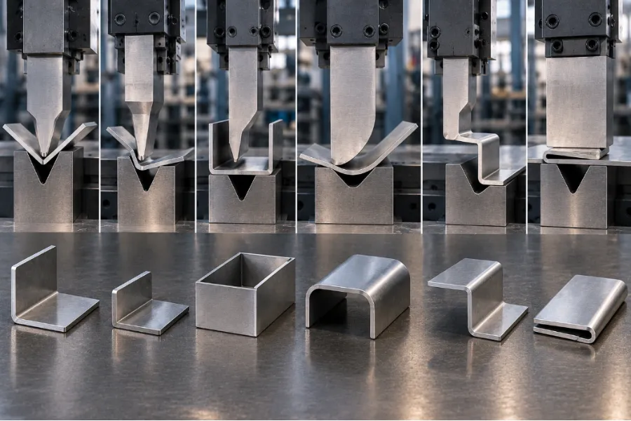
| Bending Job | Main Constraint | Typical Tooling Direction | What to Verify |
|---|---|---|---|
| General 90° bend | Radius and force | Standard punch + suitable V-die | V-opening, radius, tonnage |
| Short flange | Die support | Smaller suitable V or specialized solution | Flange support, radius, tool load |
| Deep box | Return-flange interference | Gooseneck or relieved punch | Punch clearance, daylight, removal |
| Box/enclosure | Side clearance | Segmented tooling | Segment layout and sequence |
| Large-radius bend | Target radius | Radius punch + suitable V-die | Radius consistency and force |
| Acute bend | Overbend clearance | Acute-angle tooling | Springback and clearance |
| Hemming | Prebend + flattening | Hemming tooling | Flattening force and clearance |
| Z/offset bend | Two adjacent bends | Offset tooling | Offset dimensions and orientation |
| Appearance-critical sheet | Surface marking | Mark-reducing tooling/protection | Surface quality and consistency |
| High-strength plate | Springback + load | Wider V + suitable tooling | Radius, cracking risk, tonnage |
| Thick plate | High bending force | Wider V + high-load tooling | Machine and tooling capacity |
| High-mix production | Changeover frequency | Modular or segmented tooling | Compatibility and setup time |
| Repetitive special part | Cycle consistency | Dedicated tooling where justified | Volume, setup savings, tool cost |
These are selection directions rather than fixed prescriptions. Each setup still needs to pass the radius, flange, force, machine, and interference checks.
Example: Selecting Tooling for a Stainless Steel Box Part
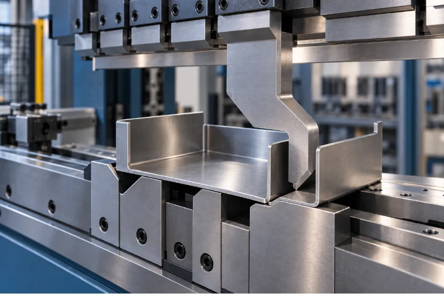
Consider a box component made from 3 mm stainless steel with 90-degree bends, a specified inside radius, a relatively short flange, and return flanges that will already be formed before the final bends.
The selection process should eliminate unsuitable combinations rather than automatically assigning a familiar V-opening.
Candidate A: Wider V-Die
A wider V-opening may reduce bending force, which can be useful for stainless steel. However, the resulting inside radius may become too large for the drawing, while the short flange may no longer have sufficient die-shoulder support.
If either condition fails, the wider V-die is rejected even if its tonnage requirement is favorable.
Candidate B: Narrower V-Die
A narrower opening may improve flange support and produce a smaller radius.
The trade-off is higher bending force and potentially greater contact pressure. The candidate remains viable only if the press brake and tooling can safely carry the resulting load.
Punch A: Straight Punch
A straight punch may have the correct angle and nose radius but still collide with the return flange.
Because the interference occurs after earlier bends have changed the workpiece geometry, the straight punch is rejected for the complete sequence.
Punch B: Gooseneck or Relieved Punch
A relieved profile provides additional clearance around the return flange.
The remaining setup must then be checked for punch height, daylight, clamping compatibility, tool load, and finished-part removal.
Final Verification
The tooling combination is acceptable only after all relevant constraints pass:
- V-opening and radius
- Minimum flange support
- Total bending force
- Tooling linear load
- Punch-to-part clearance
- Machine daylight
- Backgauge access
- Part rotation and removal
This is the central principle of tooling selection: the best tooling combination is the one that satisfies the complete set of job constraints, not the one that solves only the first bend.
Segmented, Multi-V, or Dedicated Tooling?
After suitable tooling geometry has been identified, consider how the job will be produced.
Segmented Tooling
Segmented punches and dies allow the working length to be assembled from shorter sections.
They are useful for boxes and enclosures because unnecessary sections can be removed to create clearance around existing flanges. They also provide flexibility in high-mix production.
Multi-V Dies
Multi-V dies provide several openings in one tool body and can reduce die changes when different thicknesses are regularly processed.
The die must still fit the press brake table, clamping system, and workpiece geometry. The selected V-opening must also pass the same radius, flange, and load checks as a single-V die.
Dedicated Tooling
Dedicated tooling becomes more attractive when standard tools cannot efficiently provide the required geometry or when repetitive production makes a specialized operation economically worthwhile.
For low-volume work, standard or modular tooling may remain more economical even if it requires additional operations.
When Does a Bending Job Need Special Tooling?
Some jobs remain inefficient with conventional V-bending even after standard tooling has been evaluated.
Hemming
Hemming normally combines an acute prebend with a flattening operation.
Dedicated hemming tooling can reduce setup changes for repetitive production, but the flattening load must be checked separately from the initial V-bend.
Offset and Z Bending
An offset can be produced through two conventional bends or dedicated offset tooling that forms adjacent bends in one operation.
Two conventional operations reduce special-tool investment but add positioning and dimensional-control requirements. Dedicated tooling can improve repeatability when production volume justifies it.
Small-Flange Bending
If the required flange falls below the support capability of a practical V-opening, choosing an increasingly narrow die can create excessive force, an unsuitable radius, or high contact pressure.
Specialized short-flange forming methods may be preferable when standard tooling cannot satisfy all constraints.
Mark-Free Bending
Polished stainless steel, aluminum, pre-painted sheet, coated material, and cosmetic panels can develop marks as the workpiece moves across the die shoulders.
Depending on the job, options can include an appropriate die shoulder radius, protective film, soft contact materials, or rotating/wing-style die concepts. The selected solution should still be checked for bend accuracy and tooling compatibility.
Check Press Brake Compatibility Before Finalizing the Tooling
A punch and die can be suitable for the part but incompatible with the machine.
Verify:
- Available machine tonnage
- Working length
- Stroke
- Daylight or open height
- Throat depth
- Table width
- Tool holder and clamping standard
- Required adapters or extensions
The tooling interface is part of the selection process. A geometrically suitable punch or die cannot be used if its mounting and clamping system does not securely match the press brake.
Quick-clamping systems can reduce changeover time in high-mix production, but the tooling must match the machine’s clamping interface or use an approved adapter.
Check the Bend Sequence Before Production
Tooling should be validated against the complete bend sequence rather than each bend independently.
After every operation, the workpiece geometry changes. A flange created early in the sequence may later collide with the punch, remove a usable backgauge surface, or prevent the part from rotating into the next position.
For boxes, multi-bend components, offsets, and internal bends, evaluate the sequence from the first operation through final part removal. CNC bend simulation can help identify tooling, backgauge, orientation, and collision problems before production.
Actual sheet thickness variation should also be considered when a setup operates close to a geometric or load limit. A small change in thickness can affect bending force, radius, and final angle.
Where springback, material variation, or surface quality remains uncertain, use a trial bend to confirm the final setup.
Final Press Brake Tooling Selection Checklist
Before releasing the job, confirm:
- Material type and grade
- Material thickness and applicable tolerance
- Bend length
- Target bend angle
- Required inside radius
- Bending method
- Candidate V-opening
- Minimum flange support
- Punch nose radius
- Punch angle and overbend clearance
- Punch profile and part clearance
- Required bending force
- Press brake capacity
- Punch and die load ratings
- Holder and adapter load limits
- Tool length and segmentation
- Surface-finish requirements
- Tool holder and clamping compatibility
- Machine daylight and stroke
- Backgauge access
- Complete bend sequence
- Finished-part removal
If several of these variables remain unknown, selecting tooling from material thickness alone is premature.
For a new tooling recommendation, the most useful inputs are the part drawing, material grade, thickness, bend length, target radius, accuracy requirements, and expected production quantity.
FAQ
How Do I Choose the Correct V-Die Opening for a Press Brake?
Use material thickness and bending method to establish candidate V-openings, then check each option against the required inside radius, minimum flange, bending force, material behavior, and surface requirements. Thickness-based rules such as the common 8× guideline can provide a useful starting point under suitable conditions, but they should not be treated as universal specifications.
How Do I Choose a Press Brake Punch Radius?
Evaluate the required inside radius, material thickness, material bendability, V-opening, and bending method together. For air bending, the punch nose should work with the radius naturally developed over the selected die rather than being chosen solely from the nominal drawing radius.
When Should I Use a Gooseneck Punch?
Use a gooseneck or relieved punch when a straight punch body would interfere with a return flange, box wall, or previously formed feature. Check the actual punch profile against the complete workpiece path, including bending, rotation, and finished-part removal.
How Do I Check Press Brake Tooling Load Capacity?
Calculate the bending force for the actual bend and determine how that force is distributed over the working tool length. Compare the resulting linear load with the manufacturer’s rated capacity for the punch, die, holders, adapters, and tool segments. Do not compare total machine tonnage directly with a tooling rating expressed per meter or per foot.
When Is Custom Press Brake Tooling Necessary?
Consider custom or dedicated tooling when standard tools cannot provide the required geometry, clearance, radius, offset, or process stability, or when repetitive production makes a specialized forming operation economically worthwhile. Standard and modular tooling should normally be evaluated first because they can be reused across a wider range of bending jobs.