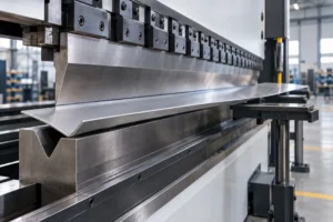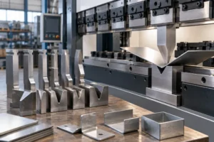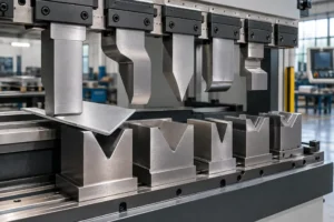
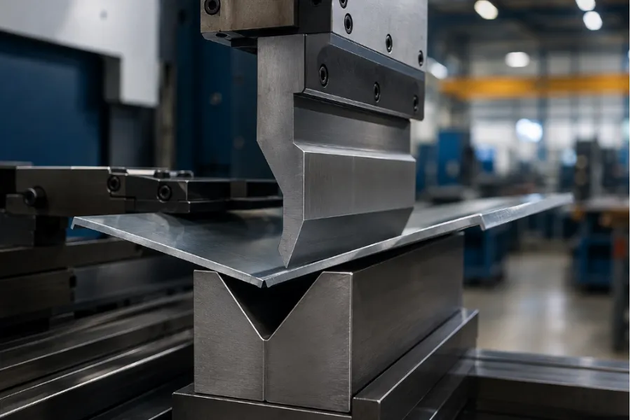
Choosing the right press brake V opening starts with material thickness, but thickness alone is not enough.
The selected die opening affects the inside bend radius, minimum flange length, required tonnage, surface marking, and flat pattern. A practical selection therefore needs to consider the bending method, material properties, part geometry, machine capacity, and tooling limits together.
A useful decision sequence is:
Bending method → Material and thickness → Initial V opening → Inside radius → Minimum flange → Tonnage → Surface requirements → Final V die
What Is a Press Brake V Opening?
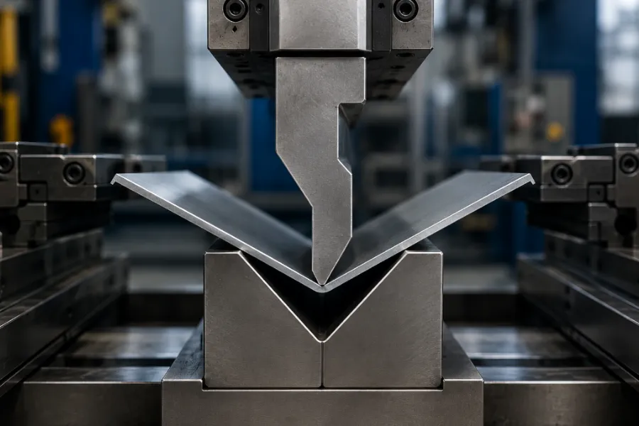
The V opening is the distance across the groove of the lower press brake die. For example, V8 indicates an 8 mm opening, while V16 indicates a 16 mm opening.
During sheet metal bending, changing this opening changes the distance between the supporting die shoulders. This directly influences how the material bends.
In general:
- A smaller V opening produces a tighter radius but requires more force.
- A larger V opening produces a larger radius and requires less force.
- A wider opening requires a longer flange to maintain proper support.
- Contact conditions at the die shoulders can also affect surface marking.
The objective is not to choose the smallest available V die. It is to find an opening that satisfies the drawing without exceeding the material, tooling, or press brake limits.
Start With the Bending Method
Before choosing a V opening, confirm whether the operation uses air bending, bottoming, coining, or another forming method.
For modern air bending of approximately 450 MPa tensile-strength steel, a commonly used starting point for thinner sheet is:
V ≈ 6–8 × material thickness
The familiar 8× rule therefore provides a convenient initial estimate.
Bottoming and coining use different tooling relationships and should be evaluated separately. Some tooling references, for example, use approximately 6×, 8×, or 10× thickness for different bottom-bending thickness ranges and around 5–6× for certain coining applications.
These are reference relationships, not universal specifications.
Why the 8× Rule Is Only a Starting Point
Suppose you are air bending 2 mm mild steel. Applying the 8× rule gives:
V = 2 × 8 = 16 mm
V16 is a reasonable candidate, but it is not automatically the final choice.
Before production, the candidate V opening should pass four important checks:
Inside radius → Minimum flange → Required tonnage → Material behavior
Thick plate and higher-strength materials may require wider openings. A short flange or tight radius requirement can push the selection in the opposite direction.
This is why professional V die selection should use thickness ratios to narrow the options rather than determine the final answer.
Check the Required Inside Bend Radius
V opening has a direct relationship with the radius formed in the workpiece.
In air bending, the sheet forms a natural inside radius influenced by the V opening and material properties. A larger V generally creates a larger natural radius, while a smaller V produces a tighter radius.
A larger formed radius also increases the radius-to-thickness ratio, which generally increases press brake springback under comparable bending conditions. This means V-die selection can affect not only the inside radius but also the final unloaded bend angle, making the V opening one variable to check when troubleshooting inconsistent press brake bending angles.
Different tooling references express this relationship differently. For example, a bottom-bending tooling reference may use:
ir ≈ V / 6
Air bending should not automatically use this relationship. Its natural radius is better understood as a material-dependent percentage of the V opening.
Therefore:
Do not select a V opening from the desired radius using one universal formula.
Material strength and ductility also matter. If the selected opening forces a material into an excessively tight radius, the outside fibers experience greater strain and cracking may occur.
The punch tip radius must also be compatible with the expected natural radius. In air bending, using a sharper punch does not necessarily mean the finished part will form to that same radius.
Check the Minimum Flange Length
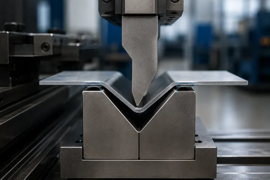
The workpiece must remain supported on the shoulders of the lower die during bending. If a flange is too short, it can lose support and slide into the V opening.
For a standard 90° V-bending reference condition, a useful practical estimate is:
b ≈ 0.7V
where b is the minimum flange length.
For a V20 die:
b ≈ 0.7 × 20 = 14 mm
This relationship can also be used in reverse.
If the shortest flange on a drawing is 14 mm:
Candidate maximum V ≈ 14 / 0.7 = 20 mm
The exact minimum flange depends on the bend angle, tooling geometry, and how the flange dimension is measured, so 0.7V should remain a reference rather than an absolute limit.
What If the Flange Is Too Short?
Simply reducing the V opening may support the short flange, but it also increases bending force and changes the expected inside radius.
Alternative solutions may include:
- Changing the bending sequence
- Using dedicated support tooling
- Using different press brake tooling geometry
- Selecting custom tooling for repetitive parts
For difficult short-flange parts, the best solution may be a process change rather than forcing the bend into a smaller standard V die.
Verify the Required Bending Tonnage
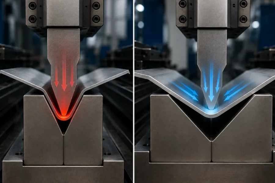
Tonnage is one of the most important checks before reducing a V opening.
In simplified form, the relationship can be expressed as:
F ∝ Rm × L × t² / V
where:
- F = required bending force
- Rm = material tensile strength
- L = bending length
- t = material thickness
- V = die opening
This relationship reveals four important rules:
- Force increases with material tensile strength.
- Force increases with bending length.
- Force increases approximately with the square of thickness.
- Force decreases as the V opening becomes wider.
If the V opening is reduced by half while the other variables remain unchanged, the required bending force approximately doubles.
Because V-die opening changes the required bending force, it can also affect machine deflection during long bends. When that deflection creates a center-to-end angle difference, press brake crowning may be needed to compensate for the change in tooling geometry under load.
Likewise, doubling material thickness can increase the theoretical force by approximately four times if the other variables remain unchanged.
For final production planning, use the press brake or tooling manufacturer’s tonnage chart or calculator because calculation constants and units vary between methods.
Always verify both the machine tonnage capacity and the tooling load capacity before approving the bend.
Adjust for Material Strength and Bendability
Material names such as “steel,” “stainless steel,” and “aluminum” are not enough to determine the final V opening.
Two sheets of the same thickness can behave differently because of differences in tensile strength, yield strength, ductility, alloy, heat treatment, and rolling direction.
Higher-strength materials generally require greater attention to minimum allowable bend radius and may require wider V openings to control outer-fiber strain.
Instead of assuming that every stainless steel or aluminum sheet uses one fixed multiplier, confirm:
- Material grade
- Tensile strength
- Yield strength when relevant
- Ductility
- Minimum allowable bend radius
- Rolling direction when important
The better engineering question is not simply, “What multiplier should I use for this material?”
It is:
Can this material safely form the required radius over the selected V opening without exceeding available tonnage?
Consider Surface Quality and Die Marking
V die selection can also affect the appearance of the finished part.
As the sheet moves across the die shoulders, friction and contact pressure can leave marks. This becomes important when bending polished stainless steel, coated sheet, appliance panels, architectural components, or appearance-grade aluminum.
A larger suitable V opening reduces required bending force and may reduce marking, but it also creates a larger natural radius and requires a longer flange.
Other options include:
- Larger or optimized die shoulder radii
- Suitable lubrication
- Protective films
- Non-marking inserts or tooling
Surface quality should therefore be considered together with geometry and tonnage rather than solved simply by selecting a wider V.
V Opening Too Small vs. Too Large
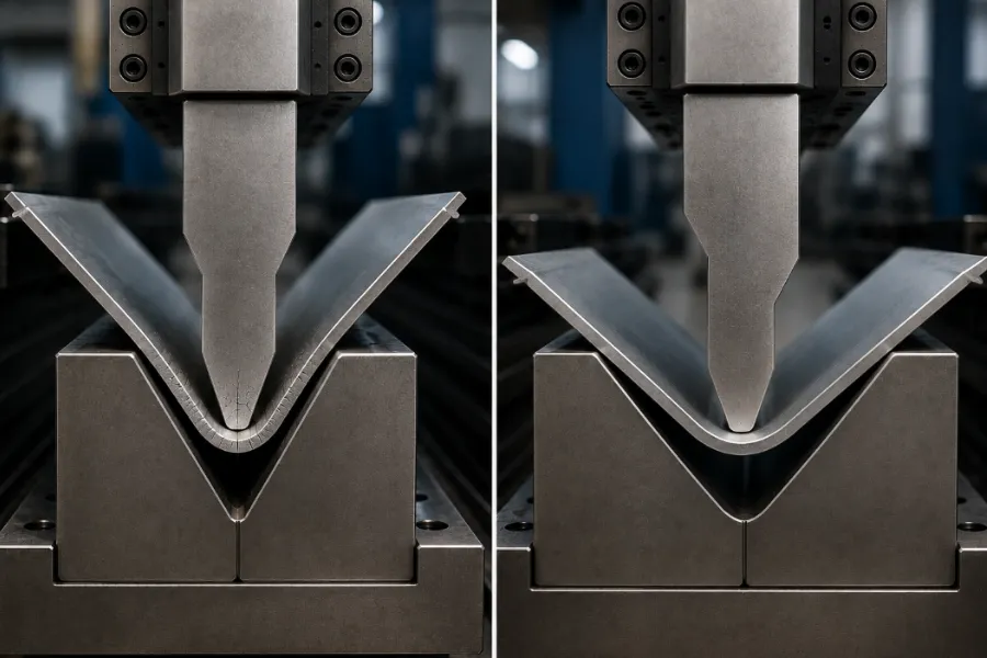
The main trade-offs can be summarized as follows:
| Factor | V Too Small | V Too Large |
|---|---|---|
| Required tonnage | Higher | Lower |
| Inside radius | Smaller | Larger |
| Short-flange support | Easier | More flange required |
| Material strain | Higher | Lower |
| Cracking risk | May increase | Generally reduced |
| Surface marking | May increase | May decrease |
| Tool load | Higher | Lower |
Neither direction is automatically better. Every adjustment should be checked against the part drawing and production limits.
Step-by-Step V Die Selection Process
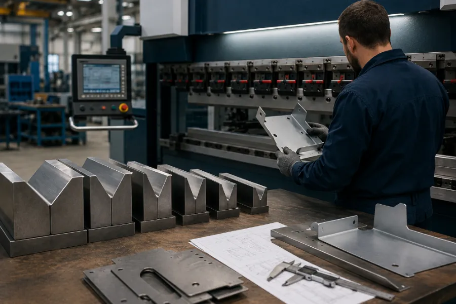
For most jobs, use the following workflow.
Step 1: Confirm the Bending Method
Identify air bending, bottoming, coining, or another process before applying a thickness-based rule.
Step 2: Confirm Material and Thickness
Use the actual material thickness and identify the grade and strength when necessary.
Step 3: Calculate an Initial V Opening
Use an appropriate thickness-to-V ratio to identify a candidate die.
Step 4: Check the Inside Radius
Confirm that the expected natural radius is compatible with the drawing and material bendability.
Step 5: Check the Minimum Flange
Make sure the shortest flange remains supported by the selected tooling.
Step 6: Verify Tonnage
Calculate the required force and compare it with both machine capacity and tooling load limits.
Step 7: Check Surface Requirements
Determine whether normal die marking is acceptable or protective tooling is necessary.
Step 8: Select the Available Tooling
Choose the nearest suitable available V opening only after understanding how the change affects radius, flange support, and tonnage.Then evaluate the V-die together with the punch profile, part clearance, tooling load, and machine compatibility when choosing press brake tooling for the complete bending job.
Practical V-Opening Selection Example
Consider a 2 mm mild steel part being air bent to approximately 90°.
Using the 8× rule as an initial estimate:
V = 2 × 8 = 16 mm
Now suppose the shortest flange is 12 mm.
Using the standard 90° reference estimate:
Minimum flange ≈ 0.7 × 16 = 11.2 mm
The 12 mm flange therefore appears compatible with V16 from a basic support standpoint.
The next checks are the required inside radius and tonnage. If the drawing requires a substantially tighter radius, simply moving to V12 should not be automatic because reducing V also increases bending force.
The engineer should recalculate tonnage, confirm that the material can tolerate the tighter radius, and verify the punch and die load capacities.
If all checks pass, V16 remains a reasonable candidate. If one constraint fails, the tooling or bending process should be reconsidered.
This is why 2 mm × 8 = V16 starts the selection process rather than finishes it.
How V Opening Affects the Flat Pattern
Changing the press brake V die can affect an upstream operation such as laser cutting.
A different V opening can create a different inside radius. Changing the radius can affect bend allowance, bend deduction, and ultimately the required flat blank dimensions.
If the laser program assumes one bend radius but the press brake produces another, the finished flange dimensions may be incorrect even when the bend angle is correct.
For repeat production, the actual V opening should therefore be considered when establishing and validating the flat pattern.
Single-V or Multi-V Die?
Multi-V tooling can reduce setup time when a job shop frequently changes material thicknesses or handles high-mix, small-batch work.
Single-V tooling can be preferable for higher-tonnage applications, longer production runs, or jobs where predictable geometry and wear control are more important.When comparing these die options with different punch profiles, see our press brake tooling selection guide.
A simple decision framework is:
Frequent changeovers and high-mix production → Consider multi-V
Higher loads and tighter production consistency → Consider single-V
The best choice depends on production conditions rather than tooling type alone.
Common V-Opening Selection Mistakes
Treating 8× as a Universal Rule
The 8× rule provides an initial estimate. It does not replace checks for radius, flange length, material strength, and tonnage.
Reducing V Without Recalculating Tonnage
A smaller opening increases bending force. Always recalculate machine and tool loads before changing to a narrower die.
Ignoring the Shortest Flange
A V opening can satisfy the thickness rule but still be unusable if the shortest flange cannot remain supported.
Changing V Without Checking the Flat Pattern
Changing the V opening can change the inside radius and therefore the bend deduction or allowance used to calculate the blank.
V-Opening Selection Checklist
Before approving a press brake die selection, confirm:
- Bending method
- Material grade
- Actual thickness
- Material strength when required
- Required bend angle
- Required inside radius
- Minimum flange length
- Bending length
- Required tonnage
- Machine capacity
- Tool load capacity
- Surface requirements
- Available V openings
- Flat-pattern implications
For a new part, the drawing and accurate material information should form the basis of the final tooling decision.
Conclusion
The right press brake V opening cannot be determined from material thickness alone.
Thickness provides a starting point. The inside radius checks the required geometry, minimum flange checks workpiece support, and tonnage verifies whether the press brake and tooling can safely produce the bend. Material properties and surface requirements then refine the final choice.
A useful selection logic is:
Thickness → Initial V → Radius → Flange → Tonnage → Material and surface requirements → Final V
For a new bending application, start with the material, thickness, bending length, part drawing, required inside radius, minimum flange, and surface requirements. These details provide a stronger basis for evaluating the appropriate tooling and machine configuration when comparing sheet metal bending machine manufacturers.
FAQ
What is the 8× rule for press brake V dies?
The 8× rule uses a V opening approximately eight times the material thickness as an initial reference, particularly for common air-bending applications. It is not universal. Material strength, radius, flange geometry, bending method, and tonnage can require a different opening.
How do I calculate V opening from material thickness?
Start with a thickness-to-V ratio appropriate for the bending method and material. For thinner steel in air bending, approximately 6–8× thickness is a common starting range. Then verify the inside radius, minimum flange, tonnage, and tooling capacity.
How does V opening affect the inside bend radius?
A larger V opening generally produces a larger natural inside radius, while a smaller opening creates a tighter radius. The exact relationship varies with material properties and bending method, so a single V-to-radius formula should not be applied universally.
How do I calculate minimum flange length?
For a standard 90° V-bending reference condition, b ≈ 0.7V is a useful practical estimate. For example, V20 corresponds to approximately 14 mm. Actual minimum flange requirements depend on the bend angle and tooling geometry.
What happens if the V opening is too small?
An undersized V opening increases required tonnage and tool load while producing a tighter radius. Depending on the material and application, it may also increase marking, tooling wear, and cracking risk.
Does a larger V opening require more or less tonnage?
Less. With the other variables unchanged, bending force is inversely related to V opening. Increasing V reduces required force, while reducing V increases it.