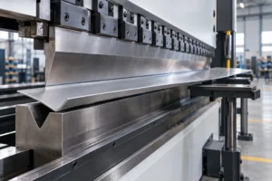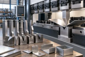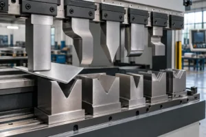
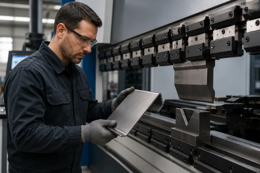
Press brake bend allowance is the developed length of the curved portion of a bend, measured along the neutral axis. It helps determine the correct flat blank before a sheet metal part is formed.
The standard formula is:
BA = (π / 180) × A × (R + K × T)
where A is the bend angle, R is the formed inside radius, K is the K-factor, and T is material thickness.
The formula provides a useful starting point. For production work, however, the actual result can also depend on material condition, formed radius, V-die opening, bending method, and tooling condition. Tight-tolerance parts should therefore be verified with a test bend.
What Is Bend Allowance in Press Brake Bending?
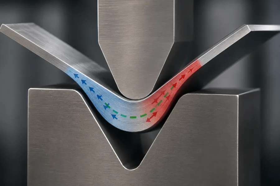
When sheet metal is bent, the material on the inside of the bend is compressed while the outside is stretched. Between these regions is the neutral axis, where the material theoretically experiences no longitudinal change in length.
Bend allowance, or BA, is the arc length of the bend measured along this neutral axis. It represents the material required to form the curved portion when converting a finished part into a flat pattern.
A single-bend flat pattern can be considered as three regions:
- First straight section
- Curved bend region
- Second straight section
If the bend allowance is incorrect, the flat blank may be too long or too short even when the final bend angle is correct. On parts with multiple bends, small errors can accumulate and affect overall dimensions.
Press Brake Bend Allowance Formula
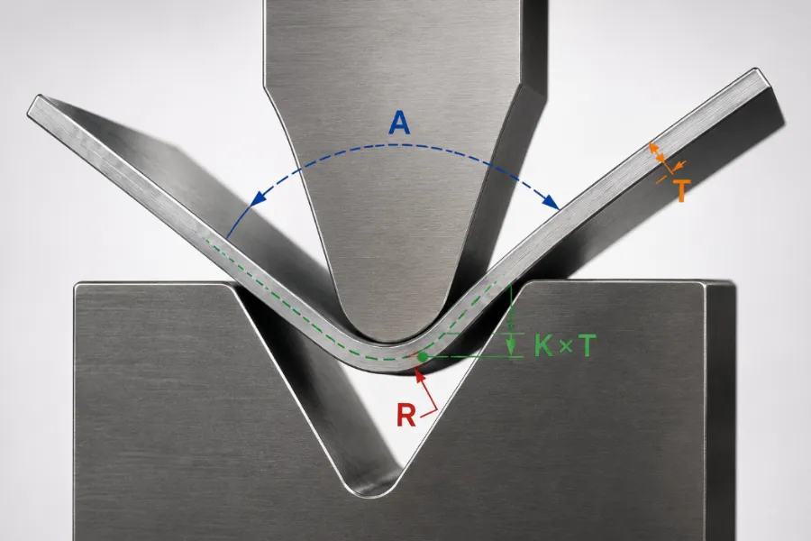
The standard geometric formula is:
BA = (π / 180) × A × (R + K × T)
| Symbol | Meaning | Unit |
|---|---|---|
| BA | Bend allowance | mm or in |
| A | Bend angle | degrees |
| R | Formed inside radius | mm or in |
| K | K-factor | Dimensionless |
| T | Material thickness | mm or in |
The expression R + K × T represents the radius of the neutral axis. Multiplying this radius by the bend angle in radians gives the developed arc length.
Keep the units consistent. If R and T are entered in millimeters, BA will be in millimeters.
Bend Allowance Formula for a 90° Bend
For a 90° bend, the equation simplifies to:
BA = (π / 2) × (R + K × T)
For example, assume:
- T = 2 mm
- R = 2 mm
- K = 0.42
- A = 90°
Then:
BA = (π / 2) × (2 + 0.42 × 2)
BA ≈ 4.46 mm
Under these assumed conditions, the curved bend region contributes approximately 4.46 mm to the developed flat pattern.
Bend Angle vs. Included Angle
The angle used in the BA formula must match the angle convention used by the calculation.
In this article, bend angle means the rotation from the original flat condition:
Bend Angle = 180° − Included Angle
| Included Angle | Bend Angle |
|---|---|
| 90° | 90° |
| 120° | 60° |
| 135° | 45° |
| 30° | 150° |
This distinction is easy to miss because a 90° bend has the same numerical value under both conventions. For non-90° bends, entering the included angle directly can produce an incorrect flat pattern.
Always check the angle convention used by your drawing, CAD/CAM software, calculator, or bend table.
What Is the K-Factor?
The K-factor represents the position of the neutral axis through the material thickness:
K = t / T
where t is the distance from the inside surface to the neutral axis and T is the total material thickness.
The relationship can be summarized as:
K-factor → neutral-axis position → neutral-axis radius → bend allowance
The K-factor should not be treated as a fixed property of a material. Material grade, thickness, inside radius, R/T ratio, bending method, and forming conditions can all affect the value used for flat-pattern development.
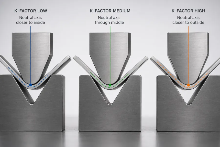
K-Factor Reference Chart
The following values are practical starting references, not material specifications or universal production values.
| Material | R/T < 1.0 | R/T 1.0–3.0 | R/T > 3.0 |
|---|---|---|---|
| Mild Steel | 0.38–0.42 | 0.42–0.46 | ≈0.50 |
| Stainless Steel | 0.40–0.44 | 0.44–0.48 | ≈0.50 |
| Aluminum | ≈0.33 | ≈0.40 | ≈0.50 |
For conventional press brake flat-pattern calculations, K-factors generally remain at or below about 0.50.
Reference values are useful for initial calculations, but repeat production or tight dimensional tolerances should be based on actual bending results whenever possible.
Bend Allowance Calculation Examples
The following examples show how changes in K-factor and bend angle affect the calculated BA.
Example 1: 2 mm Mild Steel, 90° Bend
Assume:
- T = 2 mm
- R = 2 mm
- K = 0.42
- A = 90°
Calculation:
BA = (π / 180) × 90 × (2 + 0.42 × 2)
BA ≈ 4.46 mm
The calculated bend allowance is 4.46 mm.
Example 2: 2 mm Aluminum, 90° Bend
Assume:
- T = 2 mm
- R = 2 mm
- K = 0.33
- A = 90°
Calculation:
BA = (π / 180) × 90 × (2 + 0.33 × 2)
BA ≈ 4.18 mm
The result is approximately 4.18 mm.
Material type does not appear directly in the BA formula. Its bending behavior is represented indirectly through inputs such as the selected K-factor and actual formed radius.
Example 3: 2 mm Mild Steel, 120° Included Angle
Assume the same 2 mm mild steel, but with a 120° included angle.
First convert the angle:
A = 180° − 120° = 60°
Then:
BA = (π / 180) × 60 × (2 + 0.42 × 2)
BA ≈ 2.97 mm
Using 120° directly instead of the 60° bend angle would double the calculated BA, demonstrating why the angle convention matters.
Bend Allowance Chart for Quick Reference
A bend allowance chart can speed up preliminary flat-pattern calculations, but every chart is based on specific assumptions.
The following calculated reference chart assumes:
- 90° bend
- Inside radius R = material thickness T
- Mild steel K = 0.42
- Stainless steel K = 0.44
- Aluminum K = 0.33
| Thickness | Mild Steel | Stainless Steel | Aluminum |
|---|---|---|---|
| 1.0 mm | 2.23 mm | 2.26 mm | 2.09 mm |
| 1.5 mm | 3.35 mm | 3.39 mm | 3.13 mm |
| 2.0 mm | 4.46 mm | 4.52 mm | 4.18 mm |
| 2.5 mm | 5.58 mm | 5.65 mm | 5.22 mm |
| 3.0 mm | 6.69 mm | 6.79 mm | 6.27 mm |
| 4.0 mm | 8.92 mm | 9.05 mm | 8.36 mm |
| 5.0 mm | 11.15 mm | 11.31 mm | 10.45 mm |
| 6.0 mm | 13.38 mm | 13.57 mm | 12.53 mm |
This is a calculated reference chart, not a universal production bend table.
If the actual inside radius, K-factor, tooling, or forming method differs from these assumptions, the required bend allowance can also change.
Bend Allowance vs. Bend Deduction
Bend allowance and bend deduction are related, but they are not interchangeable.
Bend allowance (BA) represents the developed arc length along the neutral axis.
Bend deduction (BD) represents the amount subtracted from the sum of outside flange dimensions to determine flat length.
For a 90° bend:
OSSB = R + T
and:
BD = 2 × OSSB − BA
Using the earlier mild-steel example:
- R = 2 mm
- T = 2 mm
- BA = 4.46 mm
Therefore:
OSSB = 4 mm
BD = (2 × 4) − 4.46 = 3.54 mm
| Bend Allowance | Bend Deduction | |
|---|---|---|
| Represents | Neutral-axis arc length | Amount deducted from outside dimensions |
| Main use | Developed bend length | Outside-dimension flat pattern |
| Interchangeable | No | No |
Before entering data into CAD, CAM, or bending software, confirm whether the system requires a K-factor, BA, BD, or bend table.
How V-Die Opening Affects Bend Allowance
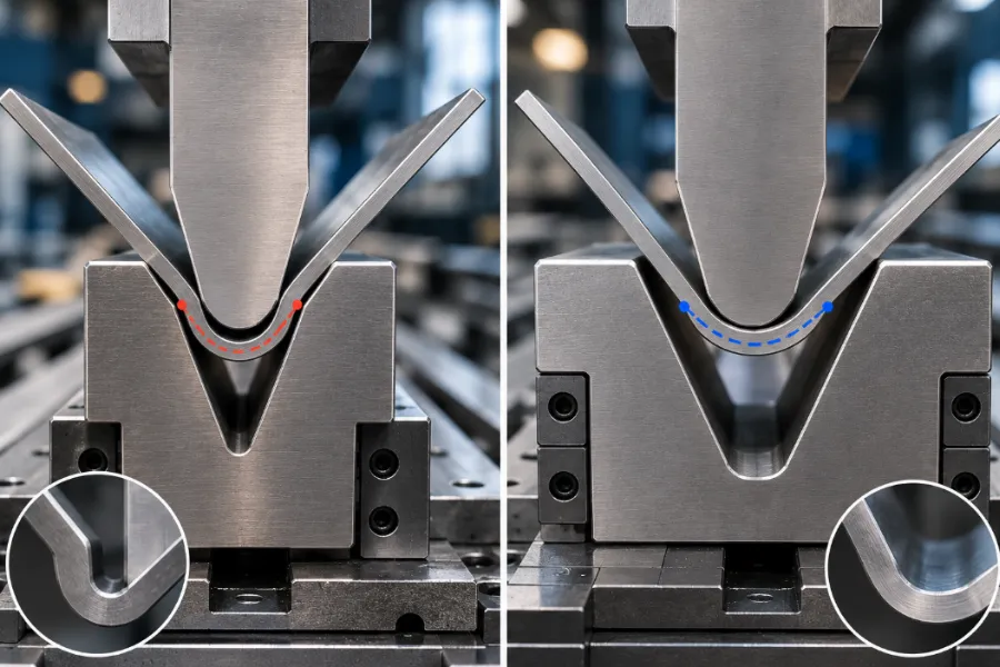
V-die opening does not appear directly in the bend allowance formula, but it can affect the formed inside radius, particularly in air bending.
The relationship is:
V-die opening → formed inside radius → neutral-axis radius → bend allowance
For standard mild-steel air bending, an opening around 8 × material thickness is often used as an initial tooling reference. However, V-opening selection varies with material, thickness, required radius, minimum flange, bending force, and tooling system.
In air bending, shop estimates for mild steel often place the natural inside radius at roughly 15%–17% of the V-opening. This is an approximation rather than a guaranteed radius.
For accurate flat-pattern work, use tooling-manufacturer data or measure the actual formed radius rather than assuming that the punch-tip radius equals the finished inside radius.
Why Calculated Bend Allowance May Differ From Actual Results
The BA formula describes geometry, while actual press brake bending also involves material and tooling behavior.
Several factors can cause the production result to differ from an initial calculation.
Material and Thickness Variation
Nominal thickness may differ slightly from actual measured thickness. Grade, temper, hardness, and batch variation can also change bending behavior.
For tight-tolerance work, actual production material provides a better basis for validation than a generic material designation.
Springback
Springback is the elastic recovery that occurs after bending pressure is removed.
It primarily affects the final bend angle rather than directly correcting flat length. Stainless steels and some aluminum alloys can show greater springback than typical low-carbon sheet steel under comparable conditions, but the actual amount depends on material grade, thickness, bend radius, and forming method.
Do not use additional overbend to hide a flat-pattern error. Check angle and flange dimensions separately.
Tooling Condition
Tool wear can gradually change the actual forming geometry.
In one supplied technical example involving 1.5 mm stainless steel and eight bends, finished dimensions differed from the developed drawing by approximately ±0.32 mm. Inspection found that the punch-tip radius had worn from about 0.2 to 0.6 mm, while the die-shoulder radius had changed from approximately 0.6 to 1.0 mm.
This illustrates why a previously validated flat pattern may require review after significant tooling wear.
How to Validate Bend Allowance on a Press Brake
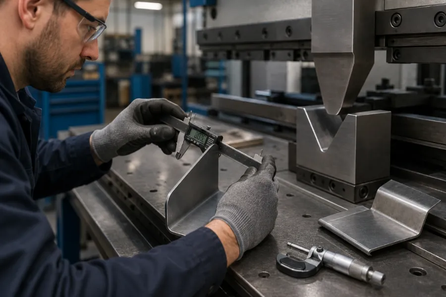
A calculated bend allowance is a starting point. For repeat production, a controlled test bend can turn that estimate into usable shop data.
Step 1: Prepare a Test Coupon
Use the same material grade and, where practical, the same batch intended for production.
Step 2: Measure Actual Thickness
Measure the coupon at several locations and record the actual thickness when dimensional tolerances require it.
Step 3: Record the Setup
Record:
- Material and actual thickness
- Punch and V-die
- Tooling condition
- Bending method
- Target angle
- Initial K-factor and BA
Step 4: Bend and Measure the Part
After unloading, check the final flange dimensions, included angle, and actual inside radius.
If the angle is wrong but the developed dimensions are correct, investigate springback and angle control. If the angle is correct but the flange dimensions are wrong, review the flat-pattern inputs and confirm that the press brake backgauge positioning is establishing the intended workpiece reference.
Step 5: Reverse-Calculate the Actual K-Factor
For a controlled 90° test bend:
BD_actual = L1 + L2 − FL_initial
OSSB = IR_actual + T_actual
BA_actual = (2 × OSSB) − BD_actual
Then:
K_true = [(BA_actual / (90 × π / 180)) − IR_actual] / T_actual
The resulting value reflects the tested bending condition rather than a generic chart assumption.
For repeat jobs, record the result together with material, thickness, punch, V-opening, formed radius, bending method, and machine setup. Building this internal bending database can reduce trial-and-error and improve consistency between design, programming, and production.
Common Bend Allowance Mistakes
Using the Wrong Angle Convention
Do not assume the included angle on the drawing is the value required by the BA formula. Confirm how the bend angle is defined.
Treating K-Factor as a Universal Constant
Reference charts are useful for initial calculations, but the same K-factor should not automatically be applied to every material and tooling setup.
Assuming Punch Radius Equals Formed Radius
The BA equation requires the formed inside radius. In air bending, this may differ from the punch-tip radius.
Changing the V-Die Without Rechecking the Flat Pattern
A different V-opening can change the formed radius. If R changes, the bend allowance can change.
Confusing Bend Allowance With Bend Deduction
BA and BD describe different geometric quantities. Verify which value your CAD/CAM system expects before entering production data.
Conclusion
Press brake bend allowance determines the developed length required through a bend and is a fundamental part of accurate flat-pattern development.
The standard formula:
BA = (π / 180) × A × (R + K × T)
provides a practical starting point, but its accuracy depends on using realistic values for bend angle, material thickness, K-factor, and formed inside radius.
For preliminary work, formulas and bend allowance charts are useful. For repeat production or tight tolerances, verify the calculation with the actual material and tooling, then store the proven bending data for future jobs.
If you are evaluating a press brake for a specific application, use the material, thickness, bending length, part drawing, bend geometry, accuracy requirements, and production volume as the basis for comparing sheet metal bending machine manufacturers and determining which machine and tooling configuration fits the application.
Frequently Asked Questions
What is the formula for bend allowance?
The standard geometric formula is:
BA = (π / 180) × A × (R + K × T)
A is the bend angle, R is the formed inside radius, K is the K-factor, and T is material thickness.
What is the bend allowance for a 90-degree bend?
For a 90° bend:
BA = (π / 2) × (R + K × T)
There is no universal BA for every 90° bend because the result changes with inside radius, thickness, K-factor, and forming conditions.
What K-factor should I use for mild steel?
A K-factor around 0.38–0.45 is commonly used as an initial reference for many mild-steel bending conditions. The correct production value depends on radius, thickness, tooling, material condition, and bending method.
For tight tolerances, validate it with an actual test bend.
Is bend allowance the same as bend deduction?
No. Bend allowance is the developed arc length along the neutral axis. Bend deduction is the amount subtracted from the sum of outside flange dimensions to calculate flat length.
For a 90° bend:
BD = 2(R + T) − BA
Does V-die opening affect bend allowance?
Yes, indirectly. Changing the V-opening can change the formed inside radius, particularly in air bending. Since R is part of the BA formula, changing the radius can change the required bend allowance.
Why does my calculated bend allowance differ from the actual part?
Common causes include an inaccurate K-factor, actual thickness variation, an incorrect assumed inside radius, material variation, V-die changes, different forming conditions, or tooling wear.
For tight-tolerance parts, use the calculation as a starting point and confirm it with a controlled test bend before full production.