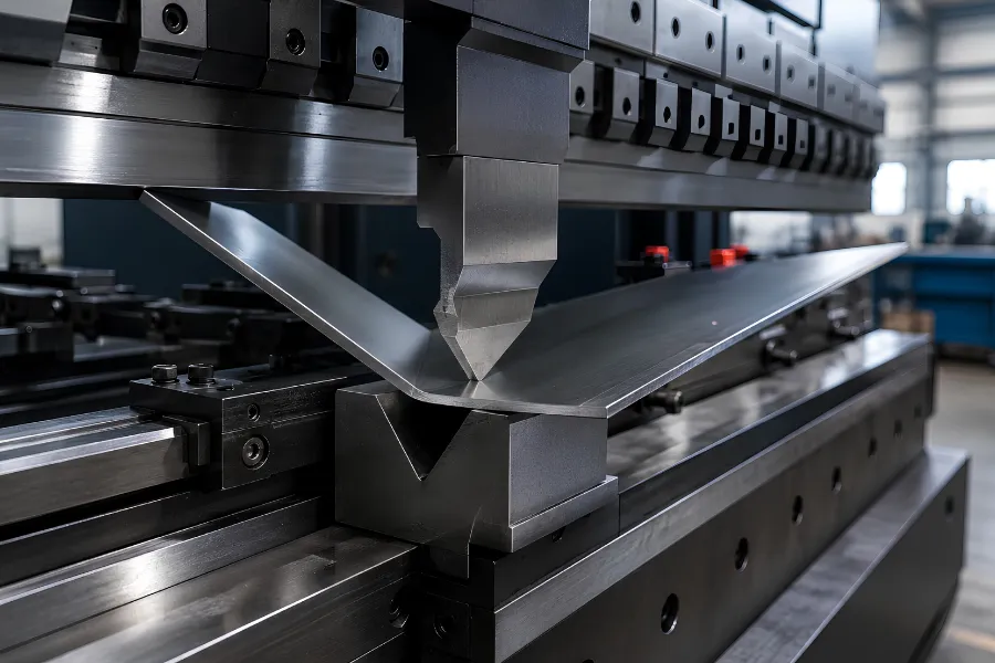
Bend deduction (BD) is the amount subtracted from the sum of the outside flange dimensions to determine the flat length required before press brake bending. It accounts for the dimensional difference created as sheet metal stretches on the outside of a bend and compresses on the inside.
For a simple one-bend part:
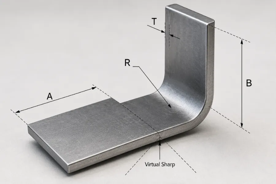
Flat Length = A + B − BD
A commonly used relationship for calculating BD is:
BD = 2 × OSSB − BA
where OSSB is the outside setback and BA is the bend allowance.
There is no universal bend deduction value for a given sheet thickness. Bend angle, inside radius, material thickness, K-factor, tooling, bending method, and actual production conditions all influence the result.
What Is Bend Deduction?
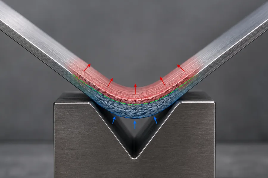
During sheet metal bending, the outer surface stretches while the inner surface compresses. Between these regions lies the neutral axis, where the material experiences essentially no longitudinal change in length.
Because of this deformation, simply adding the finished outside flange dimensions does not give the correct blank length. Bend deduction accounts for the difference:
BD = Sum of Outside Flange Dimensions − Flat Length
For example, if two outside flange dimensions total 100 mm and the required flat blank is 96 mm, the bend deduction is 4 mm.
This makes BD particularly useful when developing flat patterns from finished-part drawings, preparing laser-cut blanks, or establishing repeatable press brake processes.
Bend Deduction vs. Bend Allowance
Bend deduction and bend allowance describe related aspects of the same bend, but they are different values.
| Term | Meaning | Typical Use |
|---|---|---|
| Bend Deduction (BD) | Amount subtracted from outside flange dimensions | Flat-pattern calculation |
| Bend Allowance (BA) | Arc length through the bend along the neutral axis | Bend calculation and CAD |
| K-Factor | Ratio locating the neutral axis within sheet thickness | Used to calculate BA |
Bend allowance represents the material length contained in the bend region. Bend deduction tells you how much to subtract from the outside dimensions to obtain the flat blank.
Their relationship is:
BD = 2 × OSSB − BA
This connects bend deduction to bend allowance, outside setback, material thickness, inside radius, and neutral-axis location.
Bend Deduction Formula
The calculation can be divided into three steps.
Step 1: Calculate Bend Allowance
A commonly used bend allowance equation is:
BA = (π / 180) × θ × (R + K × T)
Where:
- BA = Bend allowance
- θ = Bend angle used by the calculation
- R = Inside bend radius
- K = K-factor
- T = Material thickness
The K-factor describes the neutral-axis position as a proportion of sheet thickness. In conventional sheet metal bend calculations, it is commonly below 0.5, but the appropriate value depends on the material and forming conditions.
Always confirm the angle convention used by your drawing, CAD system, or formula before calculating bends other than 90°.
Step 2: Calculate Outside Setback
For the angle convention used in this article:
OSSB = tan(θ / 2) × (R + T)
For a 90° bend:
tan(45°) = 1
Therefore:
OSSB = R + T
Step 3: Calculate BD
Once BA and OSSB are known:
BD = 2 × OSSB − BA
For the same angle convention, the full relationship is:
BD = 2 × tan(θ / 2) × (R + T) − BA
For a 90° bend, this simplifies to:
BD = 2 × (R + T) − BA
The resulting value can then be subtracted from the outside flange dimensions to calculate the required flat length.
90° Press Brake Calculation Example
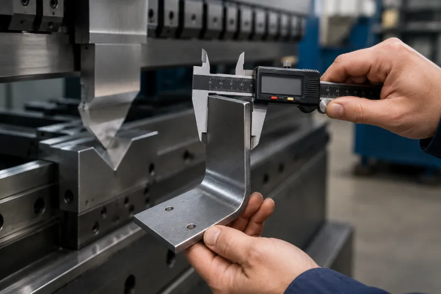
Consider a 90° bend in cold-rolled steel using these assumed values:
- Material thickness T = 0.060 in
- Inside bend radius R = 0.060 in
- K-factor = 0.38
- Bend angle = 90°
Calculate BA
BA = (π / 180) × 90 × (0.060 + 0.38 × 0.060)
BA ≈ 0.130 in
Calculate OSSB
For a 90° bend:
OSSB = 0.060 + 0.060 = 0.120 in
Calculate BD
BD = 2 × 0.120 − 0.130
BD ≈ 0.110 in
If the finished part has two outside flange dimensions of 2.000 in:
Flat Length = 2.000 + 2.000 − 0.110
Flat Length ≈ 3.890 in
This is a calculated starting value based on the assumed radius and K-factor. Tight-tolerance production should verify the result with an actual test bend.
Bend Deduction Chart for 90° Bends
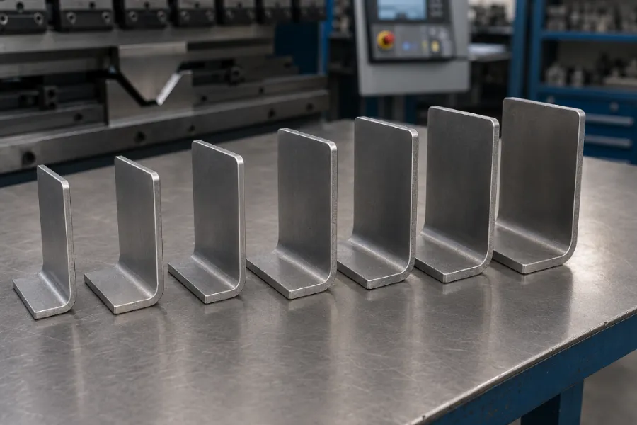
A useful bend deduction chart must state its calculation assumptions. A table containing only material thickness and BD can be misleading because thickness alone does not determine the required deduction.
The following is a calculated reference chart, not a universal press brake BD table.
Calculation conditions: 90° bend, R = T, K = 0.38
| Thickness T | Inside Radius R | K-Factor | BA | OSSB | BD |
|---|---|---|---|---|---|
| 0.5 mm | 0.5 mm | 0.38 | 1.084 mm | 1.000 mm | 0.916 mm |
| 1.0 mm | 1.0 mm | 0.38 | 2.168 mm | 2.000 mm | 1.832 mm |
| 1.5 mm | 1.5 mm | 0.38 | 3.252 mm | 3.000 mm | 2.748 mm |
| 2.0 mm | 2.0 mm | 0.38 | 4.335 mm | 4.000 mm | 3.665 mm |
| 2.5 mm | 2.5 mm | 0.38 | 5.419 mm | 5.000 mm | 4.581 mm |
| 3.0 mm | 3.0 mm | 0.38 | 6.503 mm | 6.000 mm | 5.497 mm |
For example, the 1.5 mm value does not mean every 1.5 mm sheet requires a 2.748 mm deduction. Changing the inside radius, bend angle, material behavior, K-factor, tooling, or forming method can produce a different result.
For production work, treat generic charts as reference data and use verified shop values when dimensional tolerances are important.
Factors That Change the Flat-Pattern Result
The formula is only as accurate as the inputs used. Several variables deserve particular attention.
Material Thickness and Inside Radius
Thickness appears directly in both bend allowance and outside setback calculations. The actual inside radius is equally important because it changes the geometry of the bend.
For air bending mild steel, the achieved inside radius is often approximately 15%–17% of the V-die opening, making R ≈ V/6 a useful shop-floor approximation under suitable conditions.
It is not a universal relationship. Material properties, tooling, bending method, and other forming conditions can change the actual radius.
V-Die Opening and Tooling
Press brake tooling selection, particularly the V-die choice, influences bending force, achievable inside radius, minimum flange requirements, and flat-pattern behavior.
Rules such as 6T, 8T, or 10T may be used as starting references for V-opening selection under different bending conditions. The common 8T rule is a practical guideline rather than a universal requirement.
For bend deduction calculations, the key point is that changing the V-opening may change the achieved inside radius. If the actual R changes, BA, OSSB, and BD should be recalculated.
Material Properties and Springback
When forming pressure is removed, elastic recovery causes the bend angle to open. The inside radius may also relax slightly.
If the actual radius changes after springback, the bend allowance and deduction can change as well. Material type, thickness, bend radius, and forming conditions all affect this behavior.
Bending Method
Air bending, bottom bending, and coining do not create identical forming conditions. They can produce different radii, springback behavior, and relationships between the workpiece and tooling.
A bend deduction established for one forming method should therefore not automatically be transferred to another.
Why Calculated and Actual Values Can Differ
Even when the equations are correct, real production introduces material tolerances, tooling wear, machine conditions, and process variation.
Tool wear is a good example. As punch tips and die shoulders wear, the effective bending geometry changes.
In one reference case involving 1.5 mm stainless steel and an eight-bend process, the finished dimensions differed from the developed drawing by approximately ±0.32 mm. Inspection found that the punch-tip radius had worn from about 0.2 mm to 0.6 mm and the die-shoulder radius from about 0.6 mm to 1.0 mm.
Small deviations become particularly important on parts with multiple bends because dimensional errors can accumulate and affect final size, hole alignment, assembly, and repeatability.
For this reason:
A calculated BD is a starting value. A validated BD is a production value.
How to Build a Shop-Specific BD Table
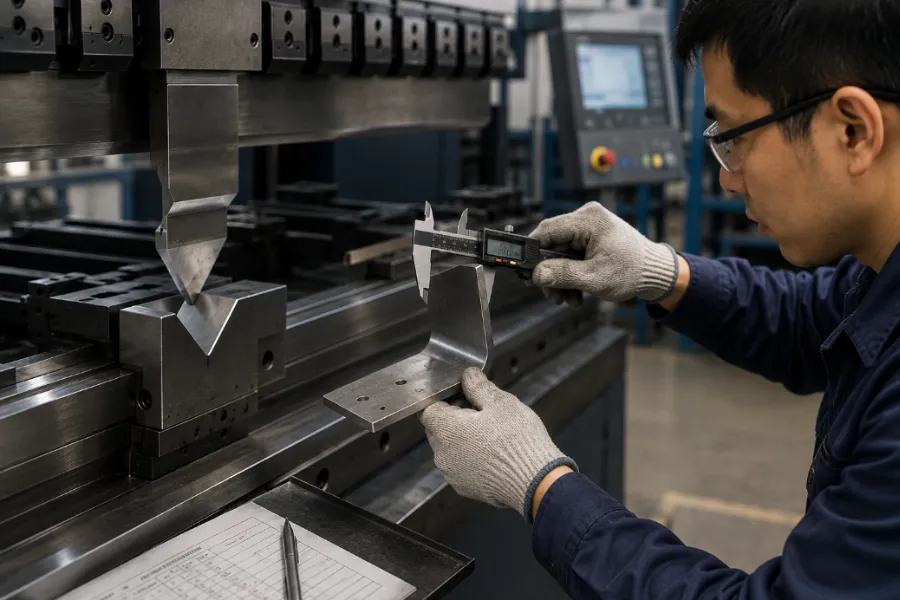
For recurring production, developing your own bend data is often more reliable than depending entirely on generic online charts.
First, establish the production conditions:
- Material and grade
- Material thickness
- V-die opening
- Punch and die configuration
- Bending method
- Target bend angle
Then make a test bend using the actual material, tooling, and press brake. Measure the finished outside flange dimensions and compare them with the original blank.
For a simple bend:
BD = A + B − Flat Length
For example, if the finished outside flange dimensions are 50.0 mm and 50.0 mm and the original flat blank is 96.2 mm:
BD = 50.0 + 50.0 − 96.2 = 3.8 mm
After repeating the test to confirm consistency, record the result with its corresponding material, thickness, V-opening, radius, angle, and tooling conditions.
Over time, this creates a shop-specific bend deduction table that can support CAD development, press brake programming, and repeat production.
Common Flat-Pattern Calculation Mistakes
One common mistake is using a bend deduction chart without checking its assumptions. A BD value should always be connected to defined geometry and bending conditions.
Another is confusing bend allowance with bend deduction. BA measures the neutral-axis arc through the bend, while BD is subtracted from the outside dimensions.
Angle convention also matters. Before calculating a non-90° bend, confirm exactly what the angle in the formula represents.
Do not assume that punch-tip radius always equals the finished inside radius, particularly during air bending. V-opening, material behavior, springback, and forming method can influence the actual result.
Finally, avoid relying indefinitely on theoretical or default CAD data. For repeat production and tighter tolerances, test bends, actual measurements, and tooling-condition checks provide a stronger basis for flat-pattern development.
From Formula to Reliable Press Brake Production
Bend deduction provides a practical method for converting finished outside dimensions into the blank required for press brake bending:
Flat Length = A + B − BD
Theoretical BD can be calculated from bend allowance and outside setback, but accurate production depends on using realistic inputs for material thickness, inside radius, tooling, springback, and forming conditions.
Calculated formulas and reference charts are useful starting points. For repeat or tight-tolerance work, test bends and a shop-specific BD table provide a more reliable basis for flat-pattern development, while the press brake backgauge establishes the workpiece position needed to produce the calculated flange dimensions.
If you are evaluating a press brake for a specific part, provide BENDORA with the material, thickness, bending length, part drawing, bend angles, required accuracy, and production volume. These inputs help determine an appropriate machine and tooling configuration for the application.
FAQ
What Is the Formula for Bend Deduction?
The general relationship is:
BD = 2 × OSSB − BA
For the angle convention used in this article:
OSSB = tan(θ / 2) × (R + T)
Bend allowance can be calculated as:
BA = (π / 180) × θ × (R + K × T)
How Do You Calculate Flat Length Using Bend Deduction?
For a simple one-bend part:
Flat Length = A + B − BD
If the outside flange dimensions are 50 mm and 40 mm and the validated BD is 3 mm:
Flat Length = 50 + 40 − 3 = 87 mm
Is Bend Deduction the Same as Bend Allowance?
No. Bend allowance is the arc length through the bend along the neutral axis. Bend deduction is the amount subtracted from the outside flange dimensions to determine flat length.
They are related through:
BD = 2 × OSSB − BA
Does Bend Deduction Change With Material Thickness?
Yes, but thickness alone does not determine BD. Inside radius, bend angle, K-factor, material behavior, tooling, and forming conditions can also change the result.
Does V-Die Opening Affect Bend Deduction?
Yes, indirectly. The V-opening can influence the inside radius produced during bending. If the achieved radius changes, the appropriate bend allowance and bend deduction can also change.
Should I Use a Bend Deduction Chart or K-Factor?
Both have useful roles. A K-factor can be used to calculate bend allowance and BD for different geometries, while a validated bend deduction table provides quick reference values for known production conditions.
For repeated or high-accuracy work, shop-tested data tied to the actual material, thickness, tooling, angle, and bending method is preferable to an unverified generic chart.