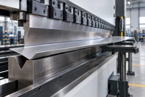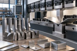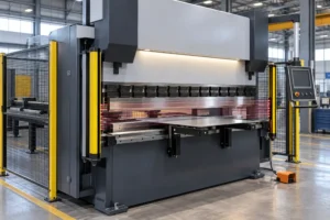
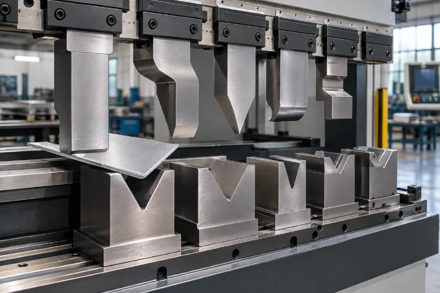
Press brake tooling consists primarily of an upper punch and a lower die that work together to form sheet metal. The tooling combination affects bend angle, inside radius, minimum flange, required force, workpiece clearance, surface marking, and repeatability.
The main press brake tooling types include standard punches, gooseneck punches, acute and radius punches, single-V and multi-V dies, hemming tools, and special-form tooling. Selecting between them requires considering the part geometry, material, bending method, machine capacity, and tooling load limits together.
Quick answer: Select press brake tooling by checking the part drawing, material and thickness, bending method, inside radius, V-opening, minimum flange, punch clearance, bending force, tooling load rating, working length, and machine interface.
What Is Press Brake Tooling?
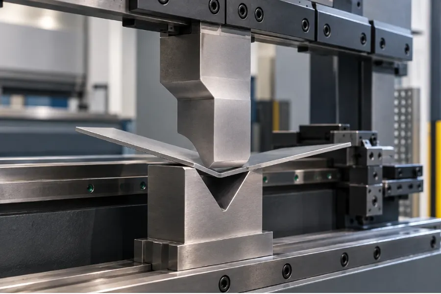
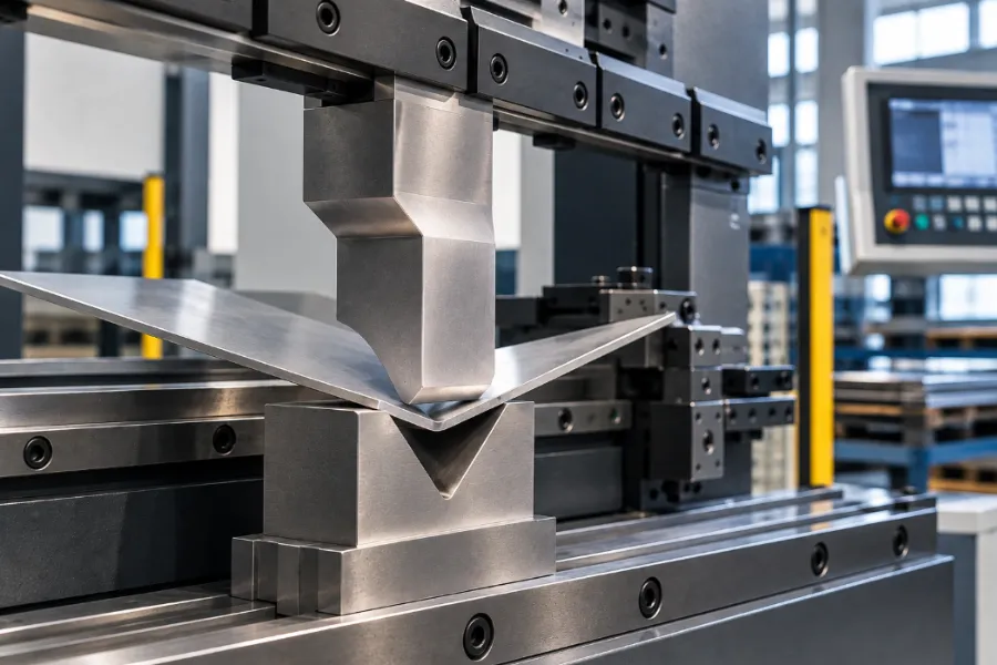
Press brake tooling is the interchangeable forming equipment installed between the ram and table of a press brake. The punch applies force from above, while the die supports the sheet and provides the opening into which the material bends.
Punch geometry determines how the tool contacts the workpiece and whether previously formed features can clear the tool. Die geometry affects material support, natural bend radius, required force, and surface contact.
Tool profile and tooling interface are separate considerations. Straight, gooseneck, acute, and radius describe punch geometry, while American-style, European-style, and WILA/Trumpf-style systems describe different mounting and clamping interfaces.
A punch can therefore have the correct forming profile but still be incompatible with the machine’s holder or clamping system.
Common Types of Press Brake Punches
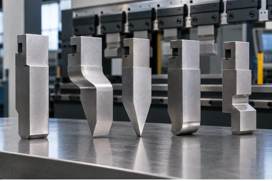
Punch selection should begin with workpiece geometry and clearance. A specialized punch is useful when its profile solves a specific forming or interference problem.
Standard or Straight Punch
A straight punch is a general-purpose option for many air-bending operations. Its relatively robust cross section and direct load path make it suitable when the workpiece does not require additional clearance around the punch body.
For a simple L-shaped bend, a straight punch is often sufficient if its angle, nose radius, height, and load rating satisfy the application.
Gooseneck Punch
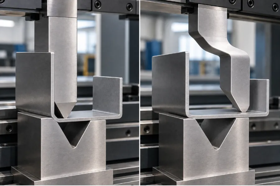
A gooseneck punch has a relieved body that provides clearance for previously formed flanges. It is commonly used for boxes, channels, U-shaped profiles, and return-flange applications.
The relief also changes the structural cross section of the punch. A deeply relieved profile may have a lower allowable load than a more robust straight punch, so the actual load rating must be checked before applying the required bending force.
Acute-Angle Punch
An acute punch has an included angle below 90 degrees. It is useful when the required forming geometry involves an acute bend or when additional overbending is needed to compensate for springback.
The punch angle does not directly determine the finished bend angle. In air bending, the final angle also depends on punch penetration, V-die geometry, material properties, and springback.
Radius Punch
A radius punch has a larger nose radius for applications requiring a larger internal bend or reduced localized contact at the punch tip.
In conventional air bending, the V-opening and material properties usually have a major influence on the natural inside radius. When the punch nose radius is larger than the radius the material would otherwise form, the punch can exert greater influence over the resulting radius.
Punch radius should therefore be evaluated against material thickness, tensile strength, target radius, V-opening, and the tooling manufacturer’s recommendations.
Offset and Special-Form Punches
Offset, joggle, and Z-bend tooling can form geometries that would otherwise require multiple conventional bending operations.
A matched offset punch and die can produce two opposing bends during one stroke. The benefit comes from reducing operations and repositioning, but the tooling remains application-specific and must be checked for force, clearance, and dimensional requirements.
Common Types of Press Brake Dies
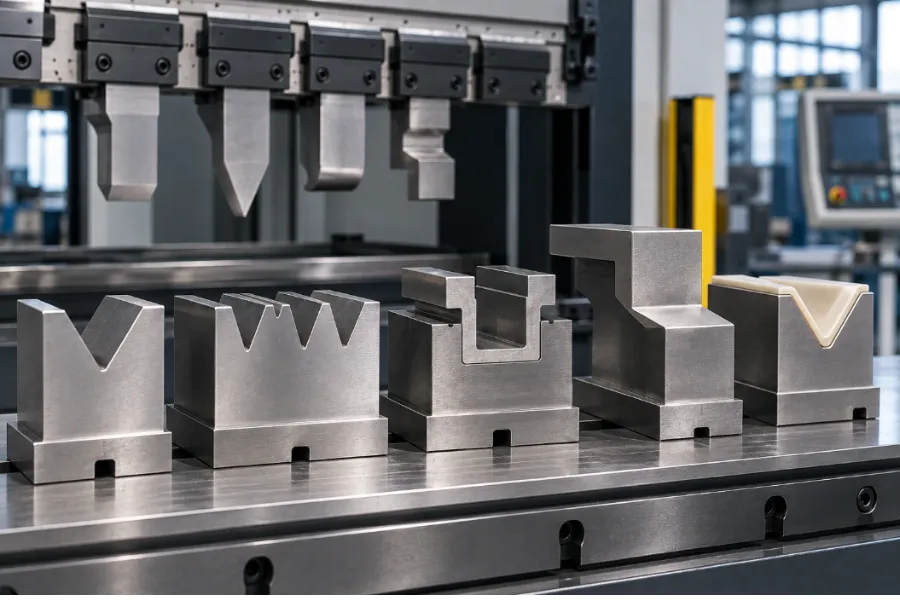
The lower die controls how the sheet is supported during forming. Its V-opening, angle, shoulder radius, height, and rated capacity must be considered together with the punch.
Single-V Die
A single-V die provides one V-opening and is widely used for air bending. Different V-openings allow the same machine to process different material thicknesses and bending requirements.
The die angle is a tooling geometry parameter, not a guarantee of the finished bend angle. In air bending, the final angle depends primarily on punch penetration, material behavior, springback, and the complete punch-die combination.
Multi-V Die
A multi-V die combines several V-openings in one lower tool. Rotating or repositioning the die allows different openings to be used without replacing the entire die.
This can reduce tool changes in high-mix production. However, the die’s overall dimensions, holder configuration, table compatibility, workpiece clearance, and rated load still need to be checked.
Flattening and Hemming Dies
Hemming normally involves an acute prebend followed by a flattening operation. Dedicated hemming tooling can combine or simplify these forming stages depending on the tool design.
The flattening operation should not be treated as an ordinary V bend because the force requirement changes significantly as the flange closes. Material thickness and the rated capacities of the tooling and machine must be checked for the complete operation.
Offset and Z-Bend Dies
Matched offset tooling can produce two opposite bends in one stroke to create a Z-shaped profile.
Compared with conventional V tooling, dedicated offset tooling can reduce repositioning and the number of forming operations. Its value depends on production volume, dimensional requirements, and how frequently the same offset geometry is produced.
Mark-Reducing Dies and Surface Protection
During conventional V bending, the sheet moves across the die shoulders as it enters the opening. This contact can leave visible marks on polished stainless steel, aluminum, prefinished sheet, or other appearance-critical surfaces.
A larger and appropriately selected die shoulder radius can reduce marking in some applications. Protective films, polyurethane materials, and specialized low-mark tooling provide additional options when surface appearance is critical.
Clean tooling is also important because particles trapped between the workpiece and die can create marks independent of the die profile.
How to Select Press Brake Tooling
Tool selection should begin with the finished part and flat pattern. The objective is to identify a tooling combination that can physically form the part while remaining within the machine and tooling limits.For a job-based selection process, see how to choose press brake tooling for different bending jobs.
Step 1: Start With the Part Drawing
Record the variables that directly affect tooling selection:
- Material type and tensile strength
- Material thickness
- Bend length
- Bend angle
- Inside bend radius
- Flange dimensions
- Return flanges and existing features
- Holes or cutouts near bend lines
- Surface-finish requirements
- Bend sequence
These parameters determine the required tooling geometry, V-opening, force, and clearance.
The complete bend sequence also matters. A punch that clears the flat workpiece may interfere with a flange created during an earlier operation.
Step 2: Identify the Bending Method
Air bending, bottoming, hemming, and special forming place different requirements on the tooling.
In air bending, the sheet does not fully conform to the bottom of the V-die. The same tooling can therefore produce inconsistent bending angles when punch penetration, material properties, springback, or tooling conditions vary between bends.
Bottoming uses substantially more contact between the workpiece and tooling. Hemming and special forming introduce additional geometry and force requirements and should be evaluated according to their specific tooling design.
Step 3: Select an Initial V-Die Opening
For many conventional air-bending applications, V ≈ 8t is a useful starting point, where V is the die opening and t is material thickness.For a detailed selection process, see how to choose the right press brake V opening.
Depending on material thickness, material grade, and bending method, tooling manufacturers may provide starting ranges around 6t to 12t. These are application guidelines rather than universal standards.
Changing the V-opening creates several simultaneous effects:
| Smaller V-Die Opening | Larger V-Die Opening |
|---|---|
| Tends to produce a smaller natural inside radius | Tends to produce a larger natural inside radius |
| Requires less flange length | Requires more flange length |
| Requires higher bending force | Requires lower bending force |
| Increases localized contact pressure | Reduces localized contact pressure |
| May increase marking risk if excessively narrow | May not achieve a required tight radius |
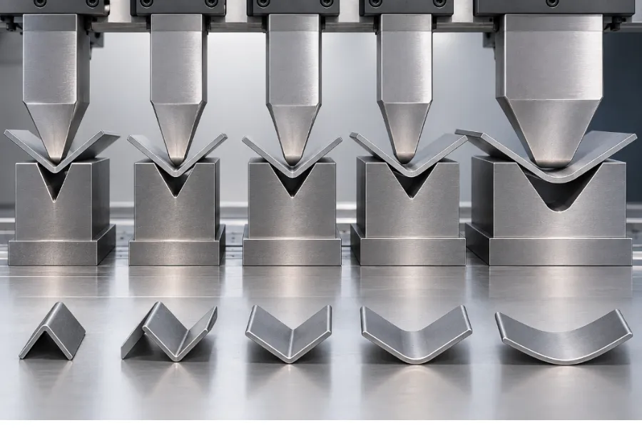
The selected opening should therefore be verified against the required radius, minimum flange, bending force, and tooling load capacity rather than material thickness alone.
How V-Opening Affects Bend Radius and Minimum Flange
V-opening directly connects several tooling decisions. A change in opening affects the natural radius, flange support, and bending force at the same time.
Inside Bend Radius
In air bending, the sheet wraps around the V-opening during forming rather than simply reproducing the punch nose radius.
For many mild-steel air-bending applications, a practical reference is an inside radius of approximately 0.16V, or about one-sixth of the die opening. Aluminum, stainless steel, higher-strength materials, thickness, grain direction, punch radius, and forming conditions can shift the actual result.For the material-dependent relationship between tooling and the formed radius, see our guide to press brake bend radius.
This relationship should therefore be treated as a starting estimate rather than a fixed material law.
If a drawing requires a smaller radius, narrowing the V-opening may increase the achievable radius control, but it also increases force and localized contact. The punch, die, material, and machine must be checked as a complete system.
Minimum Flange Length
The flange must remain supported on the die shoulders during forming. If the flange is too short relative to the V-opening, stable support can be lost as the punch enters the die.
For conventional V-die air bending, a minimum flange of approximately 0.7 to 0.8V is commonly used as a practical reference. The actual requirement depends on die geometry and should be confirmed against the tooling manufacturer’s bending chart.
If the required flange is shorter than the selected die can support, a narrower V-opening may be necessary. That change can increase bending force and reduce the natural inside radius.
Choose the Punch From Part Geometry and Clearance
After establishing an appropriate die range, select the punch according to the workpiece geometry.
Simple L-Shaped Parts
A standard punch is generally sufficient when no previously formed feature approaches the punch body.
The key checks are punch angle, nose radius, working height, clearance, and load rating.
J-Shaped and Return-Flange Parts
A return flange can collide with a straight punch during a subsequent bend even when the punch has the correct angle and nose radius.
A gooseneck or other relieved profile creates additional clearance around the existing flange. In these applications, punch selection is primarily a clearance and interference problem, not simply an angle-selection problem.
Box Bending
Box and enclosure parts introduce additional constraints because several walls and flanges can occupy the space around the punch.
Check punch height, box depth, return-flange clearance, segmented tooling arrangement, and whether the completed part can be removed after the final bend.
For complex parts, bending simulation can identify interference between the punch, die, backgauge, and workpiece before production.
Verify Bending Force and Tool Load Capacity
The selected tooling must withstand the force required to produce the bend.
Three different limits should be distinguished:
Required bending force is the force needed for the specific bending operation.
Machine tonnage capacity is the force the press brake is designed to provide under its applicable operating conditions.
Tooling load capacity is the maximum load the punch, die, or related tooling component is rated to withstand.
A press brake capable of delivering 170 tons does not mean every punch, die, holder, or adapter installed on it can safely carry 170 tons.
For conventional V bending, the general relationship is:
Required bending force ∝ (bend length × material thickness² × tensile strength) / V-opening
This means:
- Longer bends require more force.
- Higher-tensile-strength materials require more force.
- Material thickness has an approximately squared effect on the force relationship.
- Increasing V-opening generally reduces the required force.
If material thickness doubles while other variables remain comparable, the thickness-related term increases by approximately four times. In an actual production setup, the V-opening may also be increased for thicker material, so the final tonnage does not necessarily increase by exactly four times.
For final production values, use the applicable press brake or tooling manufacturer’s tonnage chart or a validated press brake tonnage calculator. Different formulas use different coefficients, units, material assumptions, and bending conditions.
The safe setup is limited by the lowest applicable rated capacity in the machine-tooling system. Check the machine, punch, die, holders, adapters, and other load-carrying components rather than verifying machine tonnage alone.
Check Tool Length and Segmented Tooling
Press brake tooling can be supplied as full-length or segmented sections. Segmented tooling allows shorter pieces to be combined into the required working length and arrangement.
It is particularly useful for:
- Box and enclosure bending
- Different bend lengths
- High-mix production
- Localized tooling arrangements
- Easier handling
- Parts requiring clearance between tool sections
Segmentation does not remove load restrictions. If different segments have different ratings, the setup must be evaluated using the applicable rating of the installed configuration rather than assuming the capacity of the strongest segment.
Confirm Machine and Clamping Compatibility
Correct forming geometry does not guarantee machine compatibility.
Before ordering or installing tooling, verify:
- Tooling tang or mounting interface
- Punch and die holder compatibility
- Manual, hydraulic, or other clamping arrangement
- Tool height
- Available stroke
- Open height
- Die holder and table configuration
- Tool retention
- Required working length
Common tooling interfaces include American-style, European-style, and WILA/Trumpf-style systems. These should be treated as compatibility specifications rather than interchangeable punch profiles.
Multi-V dies, adapters, taller tooling, and different holders can also change available forming space. Machine geometry should therefore be checked before final tooling selection, especially when comparing sheet metal bending machine manufacturers with different tooling interfaces, clamping systems, and machine configurations.
Consider Surface Finish Requirements
Surface requirements can change the tooling decision.
Polished stainless steel, aluminum, prepainted sheet, and other appearance-critical materials are more sensitive to die marks than ordinary structural parts.
Die shoulder radius, protective films, polyurethane materials, and specialized low-mark tooling can reduce visible marking. Tool and workpiece cleanliness should also be controlled because particles trapped at the contact surface can create scratches independently of the tooling profile.
When Does Special Press Brake Tooling Make Sense?
Special tooling is most useful when a repeated geometry would otherwise require additional bending operations, part flipping, repositioning, or difficult clearance arrangements.
A dedicated Z-bend tool, for example, can form two opposing bends in one stroke. The decision should consider:
- Production volume
- Number of operations eliminated
- Setup-time reduction
- Part handling
- Dimensional consistency
- Tooling cost
- Application flexibility
- Required forming force
For low-volume work with changing dimensions, standard tooling may provide more useful flexibility. For repeated geometries, the reduction in operations can justify dedicated tooling.
Press Brake Tooling Selection Checklist
| Check | Question to Answer |
|---|---|
| Material | What material and tensile strength will be bent? |
| Thickness | What is the actual sheet thickness? |
| Bend method | Is it air bending, bottoming, hemming, or special forming? |
| Angle and radius | What final angle and inside radius are required? |
| V-opening | Does it satisfy radius, flange, force, and tooling requirements? |
| Flange | Will the workpiece remain adequately supported? |
| Part geometry | Will existing features interfere with the punch or die? |
| Bend length | What working length is required? |
| Tool segmentation | Is full-length or segmented tooling more suitable? |
| Bending force | How much force does the operation require? |
| Rated capacity | Can the machine and every load-carrying tooling component handle the required force? |
| Machine compatibility | Do the interface, height, stroke, open height, and table arrangement match? |
| Surface finish | Are mark-reduction measures required? |
| Bend sequence | Can all bends be completed without collision? |
| Verification | Has the setup been confirmed with a controlled trial bend? |
Common Press Brake Tooling Selection Mistakes
Choosing the V-Opening From Thickness Alone
Using a simple thickness multiplier without checking radius, flange length, force, and tooling capacity can produce an unsuitable die selection.
Better approach: Use the thickness relationship as a starting point, then verify radius, flange support, bending force, and rated capacity.
Choosing a Punch by Bend Angle Alone
A punch with the correct angle can still collide with a previously formed flange.
Better approach: Check the complete workpiece profile and bend sequence. Use a relieved punch only when the geometry requires additional clearance.
Checking Machine Tonnage but Not Tooling Capacity
Machine capacity does not establish the load capacity of the installed punch, die, holder, or adapter.
Better approach: Compare required force against the applicable rating of every load-carrying component.
Focusing on the Punch and Ignoring the Die
The lower die affects V-opening, natural radius, minimum flange, bending force, surface marking, and material support.
Better approach: Select the punch and die as a single forming system.
Assuming Special Tooling Is Always More Productive
Dedicated tooling can reduce operations but may be inefficient for low-volume or frequently changing work.
Better approach: Compare production volume, setup savings, eliminated operations, tooling cost, flexibility, and forming requirements before committing to special tooling.
FAQ
What Is the Difference Between a Press Brake Punch and Die?
The punch is the upper forming tool that applies force to the sheet, while the die is the lower tool that supports the material and provides the forming opening. They should be selected together because punch geometry affects clearance and contact, while die geometry affects material support, natural bend radius, minimum flange, and required force.
How Do I Choose the Right V-Die Opening?
For many conventional air-bending applications, approximately eight times the material thickness is a useful starting reference. Depending on material thickness, material grade, and bending method, tooling manufacturers may provide broader starting ranges around 6t to 12t. The final V-opening should also be checked against the target inside radius, minimum flange, required bending force, material properties, and tooling load capacity.
Does the Punch Radius Determine the Inside Bend Radius?
Not necessarily. In conventional air bending, the V-opening and material properties usually have a major influence on the natural inside radius. If the punch nose radius is larger than the natural radius the material would otherwise form, the punch can have greater influence over the resulting radius. The complete punch, die, material, and bending method should therefore be evaluated together.
Can Any Press Brake Tooling Fit Any Press Brake?
No. Tooling must match the machine’s mounting and clamping interface, and its height, working length, holder arrangement, and rated load must also be compatible with the press brake. A punch with the correct forming profile is still unsuitable if it cannot be safely mounted or operated on the machine.
When Should I Use a Gooseneck Punch Instead of a Straight Punch?
Use a gooseneck or another relieved punch when a previously formed flange, return, box wall, or similar feature would interfere with a straight punch during a later bend. A gooseneck should still be checked for its load rating because its relieved cross section can reduce its allowable load compared with a more robust straight punch.