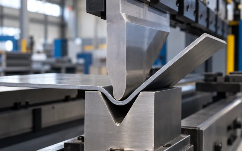
Press brake bend radius usually refers to the inside radius formed where sheet metal changes direction during bending. It affects material formability, tooling selection, bend allowance, flat-pattern accuracy, and the final dimensions of the part.
For air bending, the finished radius is not automatically equal to the punch tip radius. Instead, the V-die opening and material properties largely determine the natural inside radius.
For air bending approximately 60-KSI cold-rolled steel, a common planning estimate is:
IR ≈ 0.16 × V
A simplified rule of thumb is:
IR ≈ V / 6
where IR is the inside bend radius and V is the V-die opening.
However, these relationships provide starting estimates rather than guaranteed production values. Material strength, thickness, grain direction, bending method, tooling condition, and springback can all change the actual radius. Therefore, verify critical parts with a test bend.
What Is Press Brake Bend Radius?
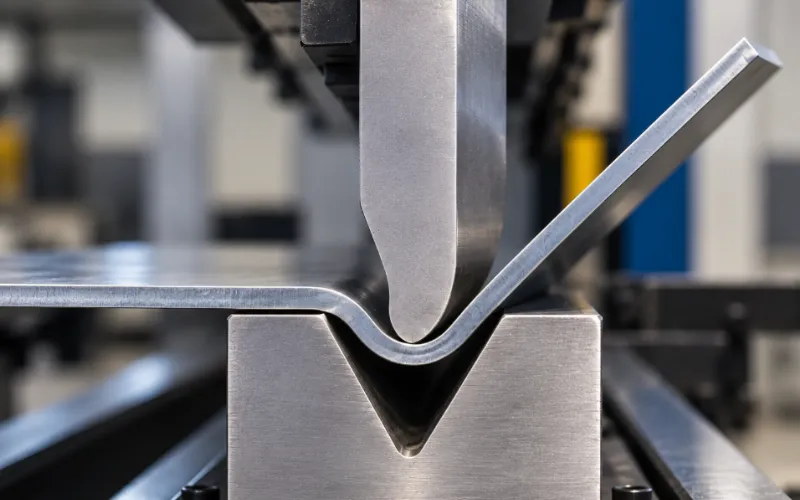
Bend radius describes the curved portion created when a press brake forms sheet metal. In press brake work, the term normally refers to the inside bend radius, or IR.
You can approximate the outside radius as:
OR ≈ IR + T
where T is material thickness.
Three radius values often cause confusion:
- Specified radius — the inside radius required by the drawing
- Punch tip radius — the radius on the nose of the upper tool
- Formed radius — the actual radius of the finished part after bending and springback
Although these values may be similar in some applications, they are not necessarily equal. In particular, the formed inside radius affects bend allowance, bend deduction, and flat-pattern dimensions.
What Determines the Inside Bend Radius?
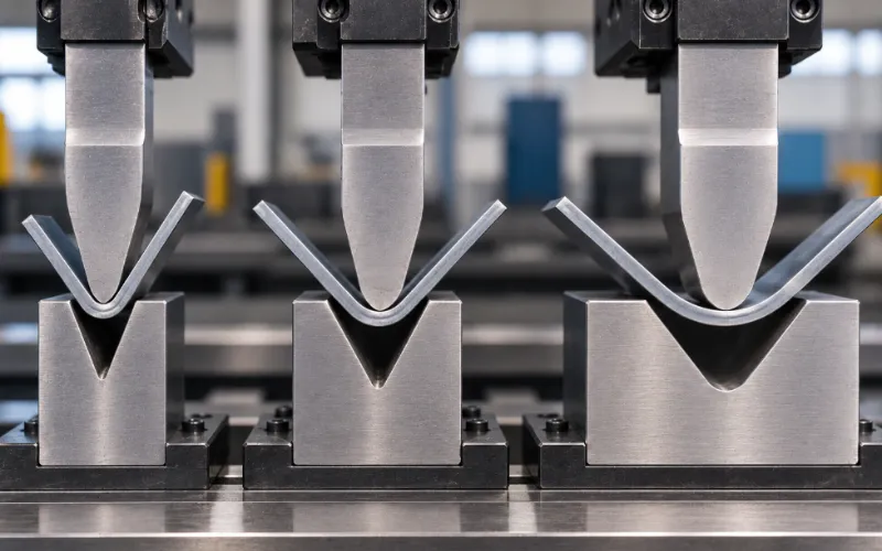
The final radius results from the interaction between material, tooling, and bending method. In air bending, the V-die opening and material properties play especially important roles.
V-Die Opening and Material
During air bending, the sheet contacts the punch and the two shoulders of the V die without fully contacting the die cavity. As a result, the material develops a natural or floated radius.
A useful planning relationship is:
IR ≈ C × V
where C is a material-dependent factor.
| Material | Typical Air-Bending Estimate |
|---|---|
| 60-KSI cold-rolled steel | 15%–17% × V |
| 304 stainless steel | 20%–22% × V |
| 5052-H32 aluminum | 11%–13% × V |
| Hot-rolled pickled and oiled steel | 14%–16% × V |
These percentages provide empirical starting points rather than material specifications. In practice, tensile strength, temper, thickness, bend angle, and springback can shift the result.
Material condition also affects how small a radius you can form without cracking. Generally, harder or less ductile materials require more conservative bend-radius selection.
In addition, grain direction affects formability. Bending parallel to the rolling direction can increase cracking risk. Therefore, you may need a larger radius when you cannot change the bend orientation.
Punch Tip Radius
In air bending, the punch tip radius usually does not directly define the finished radius when the punch radius is smaller than the material’s natural formed radius.
Nevertheless, an excessively sharp punch can penetrate or crease the material instead of producing a stable rounded bend. By comparison, tooling geometry has a much stronger influence on the final radius during bottoming and coining.
How to Calculate Press Brake Bend Radius
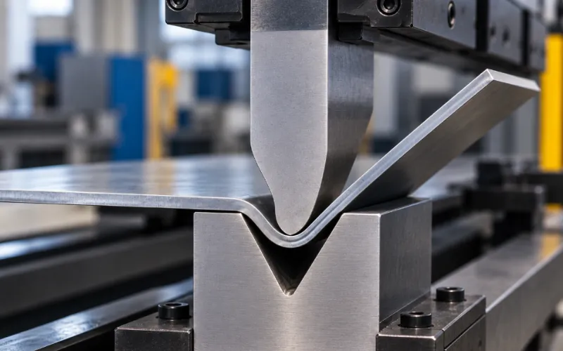
For common air bending applications, you can estimate the inside radius by starting with the V-die opening.
Calculate Radius From the V-Die Opening
For approximately 60-KSI cold-rolled steel:
IR ≈ 0.16 × V
For example, consider 3 mm mild steel bent over a 24 mm V opening:
IR ≈ 24 × 0.16 = 3.84 mm
Alternatively, the traditional V/6 approximation gives:
IR ≈ 24 / 6 = 4 mm
Both methods provide a similar planning value. However, they do not guarantee that the finished radius will measure exactly 3.84 or 4 mm.
Calculate V Opening From the Target Radius
You can also reverse the same relationship when a drawing specifies the desired radius:
V ≈ IR / 0.16
For example, a target inside radius of approximately 4 mm in the same reference material gives:
V ≈ 4 / 0.16 = 25 mm
This result provides a starting point for lower-die selection.
Next, check the calculated V opening against available tooling, flange geometry, bending force, machine capacity, and material formability.
How to Choose the Right Bend Radius
The smallest radius you can physically form is not necessarily the best radius for production. Instead, a practical selection process should balance drawing requirements, material limits, tooling, and machine capacity.
1. Start With the Drawing
First, determine whether the inside radius is a critical design requirement.
If the drawing specifies a radius that affects fit, strength, clearance, or appearance, select the bending process around that requirement. On the other hand, if the drawing does not require a specific radius, allowing the material to form its natural air-bend radius can simplify tooling and production.
2. Check Material Bendability
Minimum bend radius describes the smallest radius a material can tolerate under defined conditions without unacceptable cracking or damage.
Several factors affect this limit:
- Material grade and thickness
- Temper or hardness
- Ductility
- Grain direction
- Bending method
For critical aluminum alloys, stainless steels, and high-strength steels, use material-supplier bend data when available. This approach is more reliable than depending on a generic minimum-radius chart.
3. Evaluate the R/T Ratio
The relationship between radius and thickness helps evaluate bend severity:
R/T = Inside radius / Material thickness
A smaller R/T ratio increases tensile strain on the outside surface and therefore raises cracking risk. Conversely, a larger R/T ratio reduces local strain but can increase springback and affect flat-pattern calculations.
For this reason, you should not apply a universal “1T radius” to every material.
4. Select the V-Die Opening
For general air bending of common mild steel, the traditional 8× rule provides a useful starting point:
V ≈ 8T
For 3 mm material:
V ≈ 8 × 3 = 24 mm
Then, combine this result with the 16% radius estimate:
IR ≈ 24 × 0.16 = 3.84 mm
Importantly, the two rules serve different purposes:
- 8× rule estimates V-die opening from material thickness
- 16% rule estimates the resulting radius from the V opening for the reference material
A narrower V opening generally produces a tighter radius but requires more bending force. In contrast, a wider V opening produces a larger radius and reduces force. However, the wider opening also requires more flange length to keep the workpiece supported during bending.
5. Match the Punch and Check Machine Capacity
Choose the appropriate press brake punch and die combination to support the required forming geometry without excessively penetrating the material.
Afterward, verify bending force, bend length, press brake capacity, tooling load limits, minimum flange length, and part interference. These checks form part of the broader process for choosing press brake tooling for different bending jobs.
A practical selection sequence is:
Target radius → Material → V opening → Tooling → Required tonnage → Press brake capacity
Therefore, a radius is only practical when the complete setup can produce it safely and consistently. Tooling and workpiece geometry can also influence operator access near the bending zone, so the setup should be evaluated together with the applicable press brake guarding.
Minimum Bend Radius vs. Sharp Bend Radius
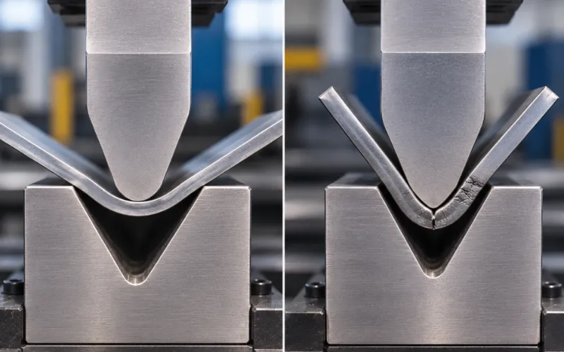
Minimum bend radius and sharp bend radius describe different limits.
Minimum bend radius relates to material formability. It indicates how tightly you can bend a specific material before cracking or unacceptable damage occurs.
A sharp bend, in contrast, describes a forming condition in which the punch begins to penetrate or crease the material instead of maintaining a smooth natural bend.
For approximately 60-KSI cold-rolled steel in air bending, a commonly referenced sharp-bend threshold is around:
IR ≈ 0.63T
However, this value is an air-bending reference point, not a universal minimum bend radius. Different alloys, tempers, thicknesses, and grain orientations can have very different forming limits.
How Bending Method Affects Bend Radius
Different press brake bending methods create the radius in different ways.
| Method | Main Radius Influence | Relative Force | Typical Use |
|---|---|---|---|
| Air bending | V opening and material | Lower | Flexible general production |
| Bottom bending | Tool geometry has stronger influence | Higher | More controlled forming |
| Coining | Punch and die geometry dominate | Very high | Specialized tight forming |
Air bending offers flexibility because one tool set can produce multiple angles with relatively low force.
In comparison, bottoming brings the material closer to the tooling geometry. Coining goes further by applying much higher pressure to plastically deform the bend region. Therefore, the best method depends on the required radius, tolerance, material, tooling, and available machine capacity.
How Springback Changes the Final Radius
Springback occurs when the material elastically relaxes after the press brake releases bending pressure.
As a result, the bend angle can open while the inside radius increases slightly. The amount of springback varies with material strength, thickness, R/T ratio, bend angle, tooling, and bending method.
For this reason, treat calculated radius values as predictions rather than exact production results.
For critical parts, bend a sample from the actual production material and allow it to relax. Then, measure the finished radius and angle. Finally, record proven values in the bending database for repeat production.
How Bend Radius Affects Part Design
Bend radius influences several features beyond the bend itself. In particular, consider cracking, nearby holes, and flange length during part design.
Cracking
Reducing the inside radius increases tensile strain on the outside surface. Eventually, excessive strain can cause cracks.
If cracking occurs, first check the radius, material condition, and grain orientation rather than simply increasing forming force.
Holes Near the Bend
Holes close to a bend can stretch or distort as material flows during forming.
One preliminary reference relationship is:
f ≈ IR + T
where f is the distance from the hole edge to the inside of the bend.
However, material, thickness, hole diameter, tolerance, and bend geometry may require additional clearance. Therefore, use this relationship as a starting reference rather than a fixed design limit.
Minimum Flange Length
A flange needs enough length to remain supported on the V-die shoulders during bending.
Because a wider V opening requires more support length, increasing the V opening to reduce tonnage or create a larger radius can make a short flange difficult or impossible to form.
Consequently, evaluate radius, V opening, and part geometry together.
How Bend Radius Affects Bend Allowance
The actual formed radius directly affects flat-pattern development.
A common bend allowance relationship is:
BA = θ × (π / 180) × (R + K × T)
where BA is bend allowance, θ is bend angle, R is the formed inside radius, K is the K-factor, and T is material thickness.
If the radius entered into CAD or CNC bending data differs from the radius produced in practice, the calculated flat length can also be incorrect. Moreover, these small dimensional differences can accumulate on parts with multiple bends.
For detailed calculations, see our guides to Press Brake Bend Allowance and Bend Deduction for Press Brake Bending.
Common Bend Radius Problems
| Problem | Possible Cause | What to Check |
|---|---|---|
| Cracks on outside surface | Radius too tight | R/T, material, grain direction |
| Radius larger than required | V opening too wide | Die selection and material |
| Visible crease at bend | Bend turning sharp | Punch radius and R/T |
| Incorrect flange dimensions | Wrong formed radius in flat pattern | Bend allowance and K-factor |
| Radius varies between parts | Material or tooling variation | Material batch, setup, tool wear |
Tool wear can also affect bend-radius consistency. As the punch tip or V-die shoulders wear, their contact geometry changes. The same variation can contribute to inconsistent press brake bending angles or gradual dimensional shifts even when the CNC program remains unchanged.
If the bend radius and angle remain consistent but the flange dimensions are incorrect, check the press brake backgauge and workpiece reference before changing the tooling or bend calculation.
Practical Bend Radius Example
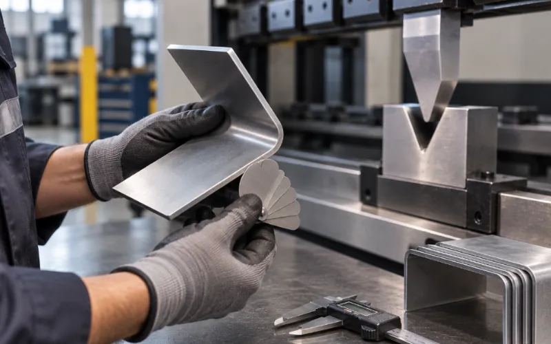
Suppose a part uses 3 mm mild steel and requires an inside radius of approximately 4 mm.
Start with the target radius:
IR = 4 mm
Next, use the 16% air-bending estimate:
V ≈ 4 / 0.16 = 25 mm
For comparison, the traditional 8× rule gives:
V ≈ 3 × 8 = 24 mm
Therefore, both approaches point toward a similar V-die range.
However, do not assume that V24 or V25 automatically solves the problem. Instead, check the available die sizes, punch geometry, minimum flange, required bending force, bend length, and press brake capacity.
Finally, perform a test bend with the actual material and measure the radius after springback. Then use the measured result to refine the production setup.
How to Validate Bend Radius Before Production
For a reliable bend-radius setup, follow this process:
- Confirm material grade, thickness, and condition.
- Check the drawing radius and tolerance.
- Estimate the natural radius and select the V opening.
- Match the punch and calculate the required bending force.
- Check flange length and other part geometry.
- Make a test bend using production material.
- Measure the final radius, angle, and dimensions after springback.
- Record the proven tooling and correction values for repeat production.
If you are evaluating a new press brake or tooling setup, provide the material, thickness, bending length, target inside radius, and part drawing. These same requirements can also be used when comparing sheet metal bending machine manufacturers, because the required tonnage, tooling, machine configuration, and bending capability should be evaluated against the actual parts you need to produce.
FAQ
What is press brake bend radius?
Press brake bend radius usually refers to the inside radius formed in sheet metal during bending. It affects material formability, tooling selection, bend allowance, and finished part dimensions.
How do you calculate press brake bend radius?
For air bending approximately 60-KSI cold-rolled steel, a common starting estimate is IR ≈ 0.16 × V, where V is the V-die opening. However, other materials require different factors, so verify the finished radius with a test bend.
Is bend radius equal to material thickness?
Not necessarily. An inside radius near material thickness can result from some common mild-steel air-bending setups. However, material properties, V opening, bending method, and design requirements ultimately determine the formed radius.
Does punch radius determine the finished bend radius?
Not usually in air bending. Instead, the V-die opening and material behavior primarily determine the natural radius. Punch geometry becomes more influential in bottoming, coining, and dedicated radius forming.
What is the minimum bend radius for sheet metal?
There is no universal minimum value. Material grade, thickness, hardness or temper, grain direction, and bending method all influence the limit. Therefore, use material-supplier data for critical applications.
How does bend radius affect bend allowance?
Bend radius is one of the variables used to calculate bend allowance. If the radius assumed in the flat pattern differs from the actual formed radius, the finished flange dimensions can also deviate from the drawing.