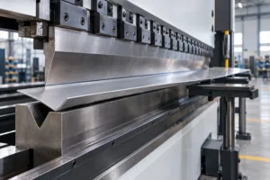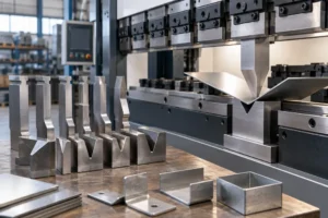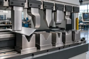
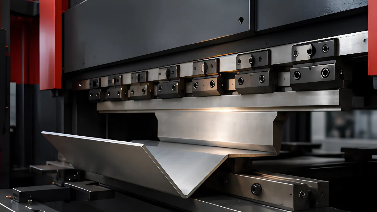
Press brake bending problems rarely come from one source. An incorrect angle may result from material variation, worn tooling, machine deflection, positioning errors, or several factors acting together.
The fastest way to troubleshoot is to start with the finished part. Identify the defect first, then work backward through the material, tooling, setup, and machine.
This guide covers common press brake bending problems, their likely causes, practical diagnostic methods, and corrective actions for more consistent sheet metal bending.
1. Why Are Press Brake Bend Angles Inconsistent?
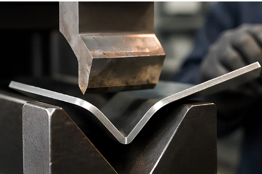
Inconsistent bend angles and dimensions are among the most common problems in press brake operation. Parts produced with the same program may show different angles, or small errors may accumulate through multiple bends until the final component falls outside tolerance.
Before changing the CNC program, check tooling wear, material thickness, tooling alignment, machine deflection, and positioning.
Tool Wear Can Change Bend Dimensions
Repeated use gradually changes the radius of punch tips and die shoulders. This changes the tooling-workpiece relationship and can affect bend allowance and finished dimensions.
One reference example involved 1.5 mm stainless steel formed through eight bending operations. An error of only 0.04 mm per bend accumulated to approximately ±0.32 mm relative to the developed dimensions. Inspection found that the punch-tip radius had worn from 0.2 mm to 0.6 mm, while the die-shoulder radius changed from 0.6 mm to 1.0 mm.
The practical lesson is simple. An error that appears insignificant in one bend can become a dimensional problem after several operations.
When dimensions begin changing, inspect punch and die wear, tooling alignment, segmented-tool joints, material thickness, and machine condition before applying CNC compensation.
2. Springback After Bending
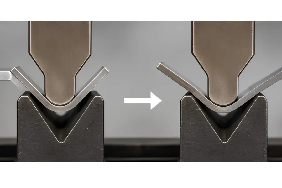
Springback occurs when the sheet partially recovers after bending pressure is removed. The material reaches one angle under load, then elastically moves toward its original shape after unloading.
Springback depends on material properties, thickness, bend radius, tooling, and forming conditions. It should therefore be treated as a process variable rather than a fixed correction value.
Under comparable tooling and thickness conditions, the reference material gives the general trend:
Cold-rolled steel < aluminum < stainless steel
Thinner material under the same tooling conditions tends to show more springback. A larger bend radius relative to material thickness can also increase elastic recovery.
How to Control Springback
A practical first step is to perform a trial bend using material representative of the production batch. Measure the relaxed angle and use the result to determine the required correction.
Depending on the application, other methods include two-stage bending, specialized corner-pressing tooling, or forming along a pre-machined V-groove.
Avoid assuming that the same compensation will work for every batch. Material thickness and mechanical properties can vary even when the nominal specification remains unchanged.
3. Why Does Sheet Metal Crack During Bending?
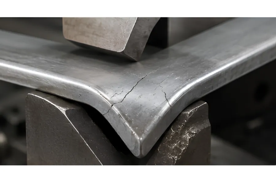
Cracks typically develop on the stretched outer side of a bend. When local tensile strain exceeds what the material can accommodate, a small crack may develop into a larger fracture or tear.
Common contributors include an excessively tight inside radius, unfavorable rolling direction, poor cut-edge condition, burr orientation, and narrow bend geometry.
Check Bend Radius and Rolling Direction
A small inside bend radius increases strain on the outer surface. Increasing the radius gives the material more room to deform and can reduce cracking.
Rolling direction also matters. The source material identifies bend orientation relative to the rolling direction as an important cracking factor, so part orientation should be considered during flat-pattern planning rather than only at the press brake.
Cut edges deserve attention as well. Deburring and improving a rough sheared or punched edge can reduce crack initiation at damaged surfaces.
For narrow bends, reducing bending speed and increasing the radius may help. Where geometry creates a severe stress concentration, an appropriate bend relief can provide another solution.
4. Scratches and Surface Marks
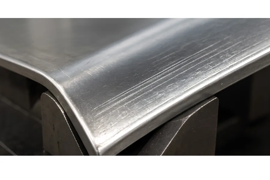
For stainless steel, aluminum, coated sheet, and other appearance-sensitive materials, a dimensionally correct part can still become scrap because of surface damage.
Press brake bending scratches can generally be divided into three types.
Sliding Scratches
These occur as the workpiece moves across the die shoulders during V-bending. Depending on the bending conditions, increasing the die-shoulder radius, reducing friction, improving the shoulder surface, or using a suitable protective material can reduce marking.
Joint Scratches
Segmented tooling can leave marks when adjacent sections have height differences or gaps. If scratches repeatedly appear at the same locations, inspect the tool joints and installation before changing bending parameters.
Ironing Scratches
These can occur when the workpiece is forced along tooling surfaces during operations such as U-bending or hat-shaped bending.
Protective sheets and non-marking tooling can help with appearance-critical parts. However, the cause should be identified first. A protective layer will not correct damaged or improperly installed tooling.
5. Hole Deformation Near the Bend
Holes located too close to the bend line may become stretched, oval, or dimensionally inaccurate.
During bending, material around the outside radius stretches. If a hole lies within this deformation zone, material movement can distort its geometry.
The reference material provides a practical starting relationship:
f = inside bend radius + material thickness
Here, f represents the distance from the hole edge to the inside of the bend.
This is a reference value rather than a universal design limit. Actual deformation depends on material, thickness, hole size, bend radius, and required tolerance.
If a hole must remain close to the bend, a properly designed relief feature can reduce the transfer of deformation into the hole. For tight-tolerance features, allow additional clearance and validate the design through trial bending.
6. Bending Bulges at Sheet Edges
A bending bulge is a local protrusion that develops where a bend reaches the edge of a sheet. Although small, it can interfere with later bending, welding, and assembly.
In box bending, two bulges may contact each other and create a gap. A bulge can also interfere with nearby holes, shafts, or mating components.
Possible corrective measures include:
- Removing the bulge after bending
- Adding a relief feature to the flat pattern
- Increasing the punch-tip radius where part geometry permits
The most economical approach is often to consider the problem during prototype and flat-pattern development. Correcting every bulge after production adds labor, while changing the bend radius later may require different tooling and setup conditions.
7. Why Is the Bend Angle Different Across a Long Workpiece?
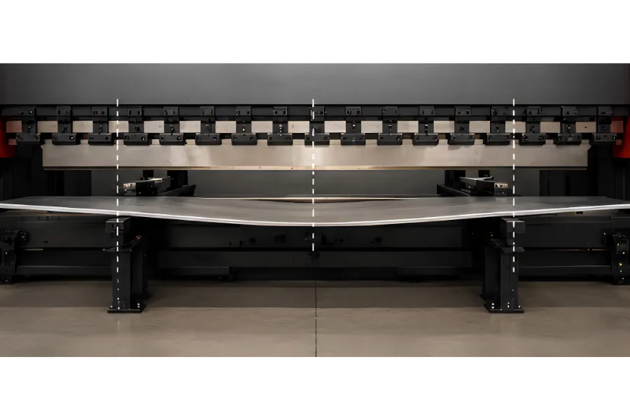
When both ends of a long bend are correct but the center angle differs, machine deflection should be investigated.
A press brake is not perfectly rigid under load. Bending force can elastically deflect the ram and bed, changing the forming condition along the tooling length.
Use a Left-Center-Right Test
Bend a representative long test piece using consistent material, tooling, and program settings. Measure the angle at:
Left → Center → Right
If both ends are approximately 90° while the center repeatedly measures around 92°, investigate deflection and crowning before applying a general angle correction.
If the error is concentrated on one side instead, inspect machine level, tooling alignment, ram-to-worktable parallelism, and synchronization where applicable.
Crowning Compensates for Deflection
Crowning introduces controlled compensation along the bending length to counter machine deformation under load.
The appropriate compensation depends on factors such as material, thickness, bending length, tooling, and bending force. The objective is not simply to make the machine straight when unloaded, but to maintain a consistent forming condition while bending.
8. Incorrect Flange Length or Bend Position
If the bend angle is correct but the flange length is wrong, the problem often points toward positioning rather than bending force.
The back gauge establishes the workpiece reference before bending. If the reference changes, the bend line moves even when the ram reaches the correct forming depth.
Check:
- Back-gauge reference and positioning
- Worn or damaged gauge fingers
- Mechanical looseness
- Workpiece contact with the reference surface
- Programmed dimensions
- Bending sequence
Multiple bends also create opportunities for small positioning errors to accumulate. Process planning should therefore consider the complete bending sequence rather than treating each bend as an isolated operation.
9. How to Troubleshoot Press Brake Bending Problems
Many press brake bending problems can be isolated without randomly changing multiple machine parameters. Use a consistent troubleshooting sequence.
Step 1. Identify the Defect
Determine whether the primary problem is the angle, flange dimension, surface finish, cracking, hole deformation, edge bulging, or variation along the bend.
Step 2. Check the Material
Measure actual thickness and check batch consistency, rolling direction, cut-edge condition, and surface condition.
Step 3. Inspect the Tooling
Look for wear, chips, rust, scratches, poor alignment, incorrect seating, and inconsistent segmented-tool joints.
Step 4. Verify Positioning
Check the back gauge, reference surfaces, workpiece placement, programmed dimensions, and bending sequence.
Step 5. Check the Machine
If the previous variables are consistent, investigate machine level, ram/worktable parallelism, crowning, synchronization, hydraulic stability where applicable, and tool mounting surfaces.
Step 6. Make a Controlled Trial Bend
Change only one variable at a time.
Changing bend depth, crowning, material correction, and back-gauge position simultaneously may produce an acceptable part, but it does not identify the original cause. Controlled testing creates a repeatable solution.
Quick Press Brake Troubleshooting Table
| Problem | Likely Causes | First Check | Typical Correction |
|---|---|---|---|
| Inconsistent angle | Material, tooling, deflection | Measure left, center, right | Isolate material, tooling, or machine cause |
| Springback | Material, thickness, bend radius | Trial bend | Adjust compensation or bending method |
| Cracking | Tight radius, rolling direction, edge condition | Inspect outer bend | Increase radius or modify orientation |
| Scratches | Tool contact, damage, contamination | Inspect mark location | Clean, protect, or modify contact |
| Hole deformation | Hole too close to bend | Check bend distance | Increase clearance or add relief |
| Bending bulge | Material flow at bend edge | Inspect bend termination | Add relief or modify geometry |
| Uneven long bend | Machine deflection | Left-center-right test | Check crowning |
| Wrong flange length | Back-gauge or reference error | Verify positioning | Correct gauge or reference setup |
How to Prevent Bending Problems Before Production
Preventing defects is usually less expensive than correcting an entire production batch.
Before production, inspect the tooling, verify material thickness and condition, confirm tooling alignment and back-gauge positioning, and review the bending program. Then perform a trial bend using material representative of the production batch.
Measure both angle and critical dimensions on the first part. For long bends, inspect several positions along the bend. For multi-bend components, monitor how dimensional variation develops through the bending sequence.
Regular machine inspection also matters. Accuracy-related components and hydraulic systems where applicable should be maintained according to the machine manufacturer’s procedures.
If recurring problems trace back to machine capacity, deflection compensation, positioning capability, or production requirements, the issue may require more than process adjustment.
When evaluating a press brake application, BENDORA considers material type, thickness, bending length, part geometry, required accuracy, and production requirements. Providing these details together with a part drawing helps determine a machine configuration based on the actual bending task rather than tonnage alone.
FAQ
Why are my press brake bend angles inconsistent?
Material thickness variation, tooling wear, alignment, machine deflection, and crowning can all affect bend angles. Compare several parts and measure different positions along the bend before changing the program.
Why does sheet metal spring back after bending?
Part of the material deformation remains elastic. When pressure is removed, the material partially recovers. Material properties, thickness, bend radius, and forming conditions determine how much springback occurs.
How can I prevent cracking during press brake bending?
Check the inside bend radius, rolling direction, cut-edge condition, and material ductility. Depending on the part, increasing the radius, changing bend orientation, improving the edge, or adding bend relief can reduce cracking.
How do I know whether the problem is the tooling or the machine?
Check material and tooling first because they are easier to isolate. If the defect remains in the same location after verifying material, tooling, and positioning, investigate machine level, parallelism, crowning, synchronization, or other mechanical factors.