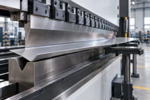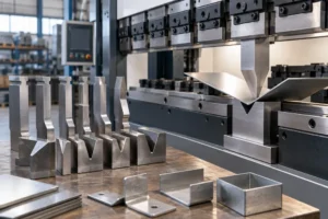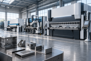
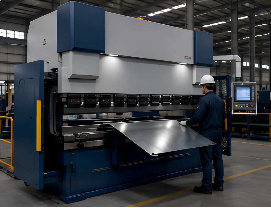
A press brake is a machine tool used to bend sheet metal and plate into predetermined angles and profiles. It applies controlled force through an upper punch and lower die, transforming flat material into components such as brackets, enclosures, panels, frames, and structural parts.
Modern press brake bending involves more than simply applying force. Material properties, tooling, V-die opening, bending force, positioning, machine deflection, and springback can all affect the finished part.
This guide explains how a press brake works, its main components and types, common bending methods, key parameters, applications, and the factors to consider when selecting a machine.
What Is a Press Brake?
A press brake forms sheet metal by positioning the workpiece between a punch and die and applying force along a defined bend line. As the punch moves toward the lower die, the material undergoes controlled deformation until the required angle or profile is formed.
Although 90-degree bends are common, press brakes can produce acute and obtuse angles, radius bends, offsets, hems, and other profiles when suitable tooling is used.
Machine capacity is typically described by tonnage and working length, while other important specifications include stroke, daylight, throat depth, backgauge travel, and working height.
Modern CNC press brakes add programmable control to the bending process. Depending on the machine configuration, the CNC system can coordinate ram position, backgauge movement, bend sequences, and compensation settings to improve repeatability.
How Does a Press Brake Work?
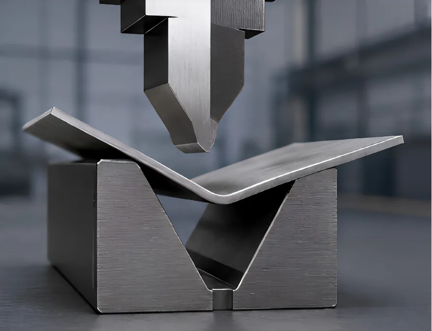
The bending process begins by positioning sheet metal over the lower die. A backgauge establishes the bend location so the workpiece is correctly aligned with the tooling.
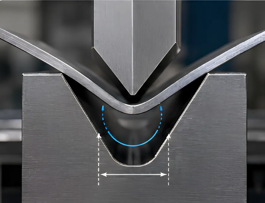
The ram then moves the upper punch toward the material. As the punch presses the sheet into the V-die, the inside of the bend is compressed while the outside is stretched. Once the material passes its elastic range and enters plastic deformation, a permanent bend remains after the load is removed.
However, the material does not remain exactly where the punch leaves it. After pressure is released, it normally recovers slightly toward its original shape. This is known as springback.
Springback varies with material, thickness, bend radius, tooling, and final angle. Under comparable tooling and thickness conditions, the supplied technical reference indicates an increasing springback tendency from cold-rolled steel to aluminum and then stainless steel.
Modern bending systems compensate for this behavior through controlled punch penetration, appropriate tooling, CNC programming, and, on suitably equipped machines, angle measurement and compensation technologies.
What Are the Main Parts of a Press Brake?
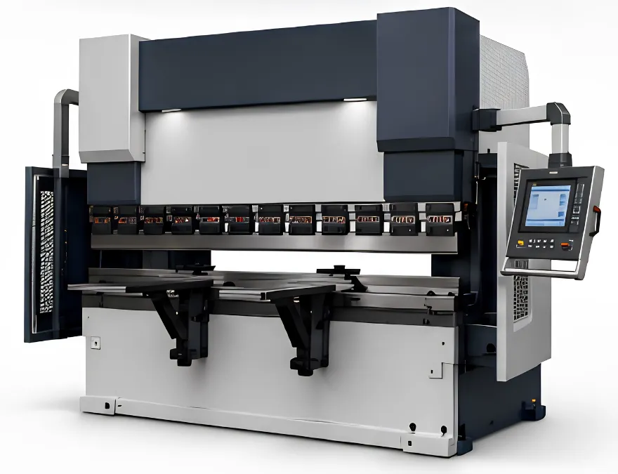
A press brake combines a rigid machine structure, drive system, tooling, positioning equipment, and controls. These components work together to determine bending capacity and consistency.
Frame, Ram, and Bed
The frame supports the forces generated during bending. The ram carries the upper punch and moves vertically during the bending cycle, while the bed supports the lower die.
Because significant loads are transferred through these structures, rigidity is important for maintaining consistent bending conditions.
Punch and Die
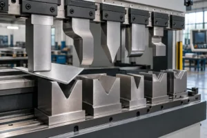
The punch is the upper tool that applies force to the workpiece, while the die supports and shapes the material from below.
Punches are available with different tip angles, radii, and profiles. Gooseneck punches, for example, provide clearance for previously formed flanges.
V-dies are widely used for general sheet metal bending. Their opening width affects required tonnage, bend radius, minimum flange dimensions, and the way material flows during forming.
Backgauge
The backgauge positions the workpiece relative to the tooling and determines where the bend occurs.
Modern CNC press brakes may use multi-axis backgauges that automatically reposition between bends. This is particularly useful for complex parts because it reduces repeated manual measurement and improves dimensional consistency.
CNC and Crowning Systems
The CNC controller coordinates programmable machine functions such as ram position, backgauge movement, bending sequence, and compensation settings.
Crowning addresses another important issue: machine deflection. Under load, the ram and bed can deform slightly, particularly during long bends. Mechanical, hydraulic, or CNC-controlled crowning systems compensate for this behavior to help maintain a more consistent angle across the bending length.
What Are the Main Types of Press Brakes?
Press brakes can be classified according to how their bending force and ram movement are generated.
Mechanical Press Brake
Mechanical press brakes use an electric motor and flywheel to store energy. A clutch transfers this energy through a crank mechanism to move the ram.
These machines were historically important in metal fabrication, but modern production increasingly uses systems that provide more flexible control over ram position and bending parameters.
Hydraulic Press Brake
Hydraulic press brakes typically use synchronized hydraulic cylinders to control the ram.
Their combination of substantial force capacity, controllability, and wide working ranges makes them common in general sheet metal and plate fabrication. Modern CNC hydraulic machines can also integrate multi-axis backgauges, crowning, programmable controls, and other automation features.
Servo-Electric Press Brake
Servo-electric press brakes use servo motors with mechanisms such as ball screws or belt drives to generate ram movement.
They eliminate the conventional hydraulic power system and can offer precise positioning, responsive motion, lower standby energy consumption, and reduced hydraulic maintenance. They are particularly attractive for applications prioritizing repeatability, cycle efficiency, and precision sheet metal work.
Hybrid Press Brake
Hybrid press brakes combine electric and hydraulic technologies. Some systems use servo motors to drive hydraulic pumps according to actual bending demand.
The objective is to retain useful hydraulic force characteristics while improving energy management, response, and process control.
Is a CNC Press Brake a Separate Type?
Not exactly. CNC describes the control system rather than the fundamental drive mechanism.
A press brake can therefore be both hydraulic and CNC-controlled, or servo-electric and CNC-controlled.
CNC technology allows manufacturers to program bend sequences, automatically reposition the backgauge, control ram movement, and recall stored programs for repeat production.
What Are the Three Main Press Brake Bending Methods?
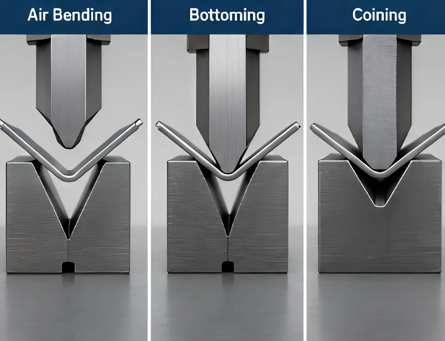
Three fundamental V-bending methods are commonly used: air bending, bottoming, and coining.
Air Bending
In air bending, also known as partial bending, the sheet contacts the tooling at three primary points: the punch tip and the two shoulders of the lower die.
The material does not fully conform to the bottom of the V-die. Instead, the bend angle is largely controlled by punch penetration.
This makes air bending flexible because different angles can be produced with the same general tooling arrangement. However, variations in material properties and springback must be considered when controlling the final angle.
Bottoming
Bottoming presses the material farther into the die so it conforms more closely to the punch and die geometry.
It can provide good bending accuracy without the extremely high forces associated with coining. Because springback still occurs, tooling angles may be selected to compensate for the expected recovery.
Coining
Coining uses substantially greater force to press the punch into the material and form it closely to the tooling geometry.
This method can provide high angle accuracy and a small bend radius while reducing the influence of springback. According to the supplied tooling reference, coining may require approximately five to eight times the tonnage of bottom bending, depending on the application.
Machine and tooling capacity must therefore be carefully checked before using this method.
What Determines Press Brake Bending Results?
Accurate sheet metal bending depends on the interaction between material properties, tooling, machine capacity, and part geometry.
Important factors include:
- Material type and tensile strength
- Material thickness
- Bend length
- V-die opening
- Inside bend radius
- Flange dimensions
- Grain direction
- Bending method
- Punch and die geometry
V-Die Opening and Bend Geometry
The V-opening has a direct influence on bend geometry and required force.
The supplied tooling reference recommends different V-opening relationships depending on the bending method and material thickness. For example, bottom bending may use approximately 6 × material thickness for 0.5–2.6 mm material and 8 × thickness for 3–8 mm material.
Two useful relationships from the same reference are:
Minimum flange length: b ≈ 0.7 × V
Inside radius: iR ≈ V / 6
These should be treated as practical reference relationships rather than universal rules. Actual results depend on material properties, tooling, and bending conditions.
Tonnage and Bending Force
Tonnage represents the available bending force of the press brake.
Required force generally increases with bending length and material tensile strength. Under the supplied reference relationship, it also increases approximately with the square of material thickness and decreases as the V-die opening becomes wider.
This means a relatively small increase in plate thickness can create a much larger increase in required bending force.
For reliable machine selection, tonnage should therefore be calculated from the actual material, thickness, bending length, V-opening, and bending method rather than estimated from thickness alone.
What Materials Can a Press Brake Bend?
Press brakes commonly process mild steel, stainless steel, aluminum, and other formable sheet metals and plates.
The same machine setup will not necessarily produce identical results across different materials. Tensile strength, ductility, grain direction, and springback behavior influence the required force and finished bend.
Grain direction is particularly important when cracking is a concern. The supplied technical reference notes that bending parallel to the rolling direction can increase cracking risk in some applications.
Material characteristics should therefore be considered when selecting the V-opening, punch radius, bending force, and process settings.
What is a Press Brake Used For?
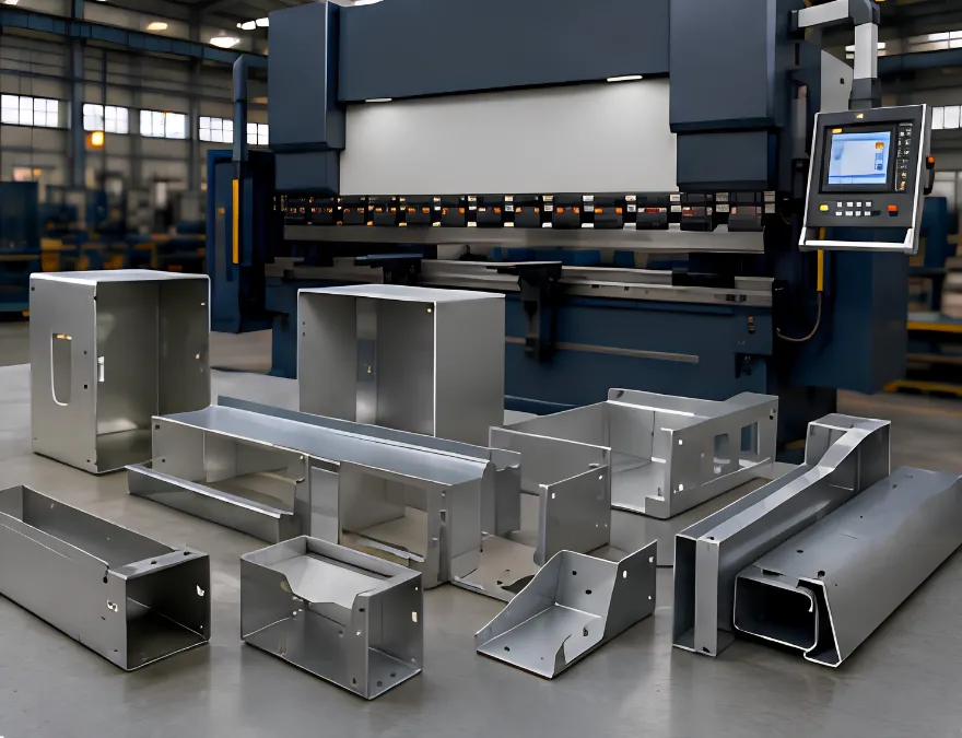
Press brakes are used throughout manufacturing to convert flat metal into functional three-dimensional components.
| Industry | Typical Applications |
|---|---|
| Automotive | Brackets, chassis parts, structural reinforcements |
| Construction | Roofing, structural components, frames, HVAC ductwork |
| Aerospace | Formed sheet and structural components |
| Electrical | Cabinets, junction boxes, enclosures, panels |
| Appliances | Housings, shells, brackets, structural panels |
| Electronics | Equipment enclosures, chassis, cabinets |
| Furniture | Frames, shelving, desks, metal cabinets |
| General fabrication | Channels, covers, brackets, frames, custom parts |
Machine requirements can vary significantly between these applications. A manufacturer producing small electrical enclosures has different tonnage, working length, tooling, and automation requirements from a heavy fabricator bending long steel plate.
How to Choose the Right Press Brake
Press brake selection should begin with the parts that will actually be manufactured.
Tonnage and working length are two primary considerations. The machine needs sufficient force for the material and tooling while providing enough bending length for the largest intended workpiece.
Material thickness, tensile strength, V-opening, bend radius, and production volume should also be evaluated. More complex components may require CNC control, multi-axis backgauges, crowning, quick tooling systems, sheet supports, or robotic integration.
Key selection factors include:
- Maximum and typical material thickness
- Material type and tensile strength
- Maximum bend length
- Required tonnage
- Bend radius and flange dimensions
- Part complexity
- Accuracy requirements
- Production volume
- Backgauge configuration
- CNC capabilities
- Tooling compatibility
- Safety and automation requirements
Machine capacity should therefore be matched to the complete bending application rather than selected from tonnage alone.
For application-specific projects, BENDORA Machinery, a Press Brake & Sheet Metal Machinery provider, can evaluate material, bend length, tonnage, tooling, control configuration, and production requirements when matching equipment to a sheet metal fabrication process.
Common Press Brake Bending Problems
Even with a correctly configured machine, material variation, tooling condition, and process settings can affect bending quality.
Springback changes the angle after bending force is removed. Compensation may require adjusting punch penetration, tooling angle, or CNC parameters.
Surface scratches can occur as the workpiece moves across the shoulders of the lower die. This is particularly important when bending stainless steel, aluminum, coated sheet, and other appearance-sensitive materials.
Cracking can develop when the outer surface of the bend exceeds the material’s forming capability. Increasing the inside radius, considering grain direction, and selecting suitable tooling can help reduce the risk.
Angle and dimensional variation may result from springback, material thickness variation, machine deflection, tooling wear, or incorrect setup. Regular tooling inspection and controlled process settings are therefore important for repeat production.
Conclusion
A press brake is not simply a machine that forces metal into a die. It is a controlled sheet metal forming system in which material properties, punch and die geometry, V-opening, tonnage, positioning, machine rigidity, and CNC control work together.
Understanding these fundamentals helps manufacturers evaluate bending processes and choose equipment more effectively. Rather than selecting a machine based only on maximum tonnage, start with the actual material, thickness, bend length, geometry, accuracy, and production volume required by the parts.
Press Brake FAQ
What is a press brake used for?
A press brake bends sheet metal and plate into predetermined angles and profiles. Typical products include brackets, enclosures, frames, channels, panels, cabinets, and structural components.
What is the difference between a press brake and a bending machine?
A press brake is a specific type of metal bending machine that normally forms straight bends using a punch and die. Bending machine is a broader term that can also include folders, roll benders, tube benders, and other forming equipment.
What is the difference between a CNC and hydraulic press brake?
Hydraulic describes how the machine generates and controls ram movement, while CNC describes the computer control system. A modern machine can therefore be both a hydraulic press brake and a CNC press brake.
How thick can a press brake bend?
There is no universal maximum thickness. Bending capacity depends on machine tonnage, material tensile strength, bend length, V-die opening, tooling, and bending method. These factors should be evaluated together for the actual application.
How much press brake tonnage do I need?
Required tonnage depends mainly on material thickness, tensile strength, bend length, V-opening, and bending method. Because force demand increases significantly as material becomes thicker, tonnage should be calculated for the actual bending conditions rather than estimated from thickness alone.