PRESS BRAKE MACHINES

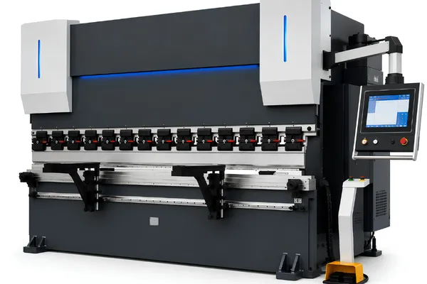
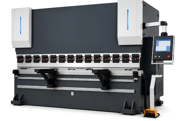
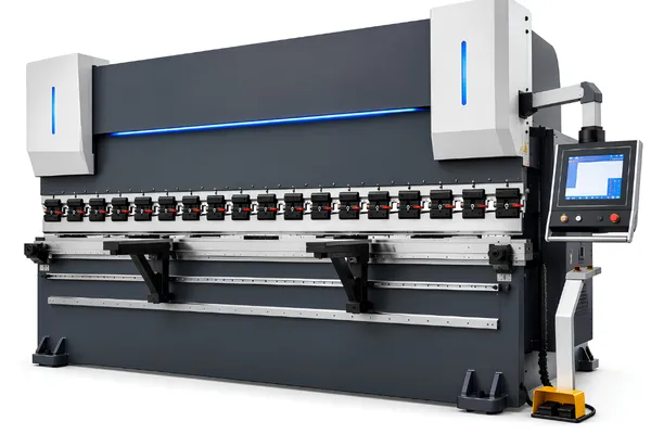
CNC Hydraulic Press Brakes

BENDORA CNC hydraulic press brakes combine electro-hydraulic synchronized control with CNC-controlled positioning for reliable, repeatable sheet metal bending. Available in multiple bending forces and working lengths, the range is designed for general fabrication through medium-heavy production requirements.

CNC Hydraulic Press Brake Models

BH-11032

  • 110 t Bending Force
  • 3,200 mm Bending Length
  • CNC-Controlled Backgauge
  • Electro-Hydraulic Synchronized

BH-17032

  • 170 t Bending Force
  • 3,200 mm Bending Length
  • CNC-Controlled Backgauge
  • Electro-Hydraulic Synchronized

BH-22040

  • 220 t Bending Force
  • 4,000 mm Bending Length
  • CNC-Controlled Backgauge
  • Electro-Hydraulic Synchronized

Why Choose BENDORA

From manufacturing and quality control to engineering and after-sales support, BENDORA focuses on reliable machine performance throughout the equipment lifecycle.

Built for Consistent Press Brake Production

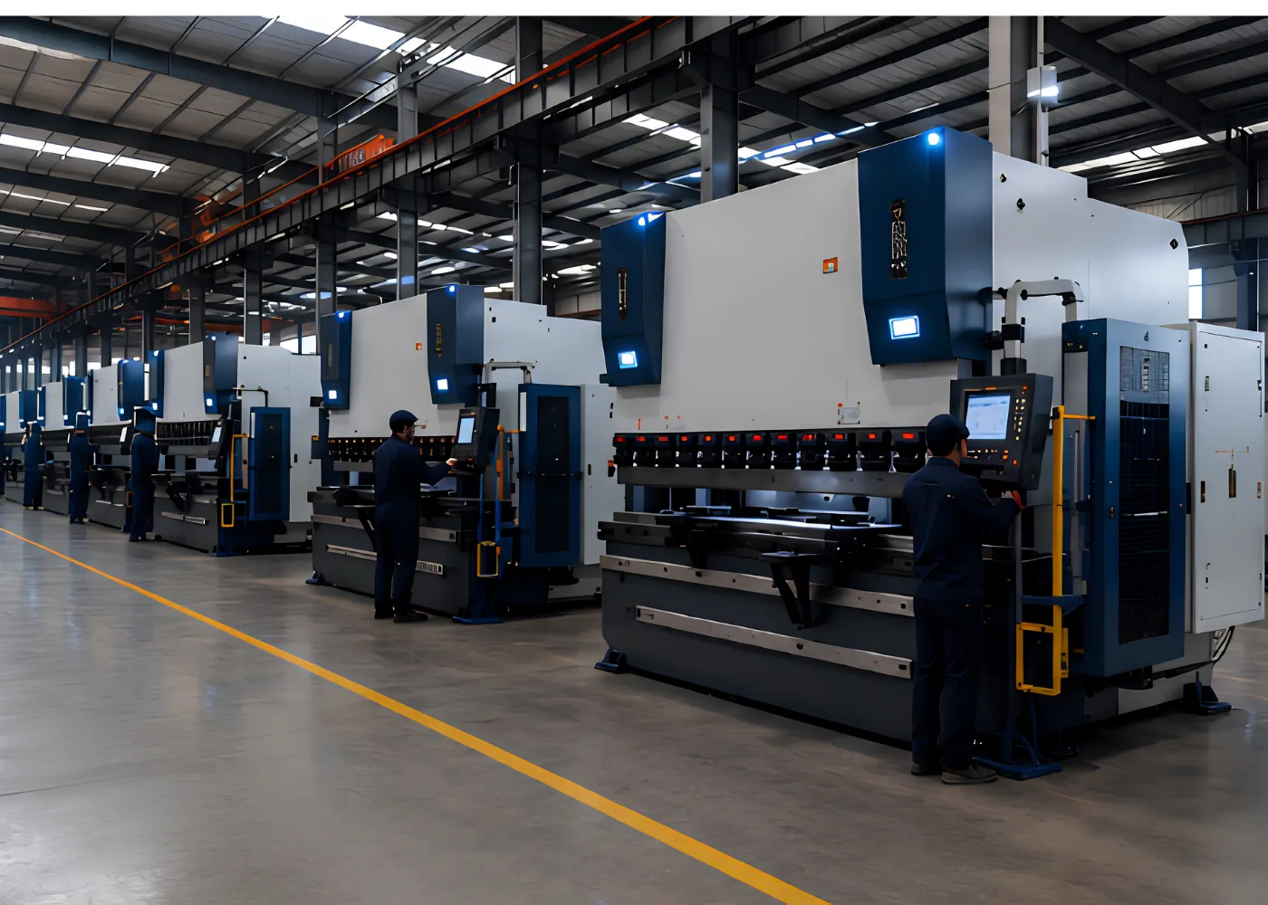
BENDORA integrates frame fabrication, precision machining, machine assembly and final testing to maintain consistent manufacturing control from structural components to completed press brakes.

15+
Years of Experience
32,000 m²
Manufacturing Facility
1,200+
Machines / Year
30+
Engineers
100%
Pre-Shipment Testing

Quality Checked Before Delivery

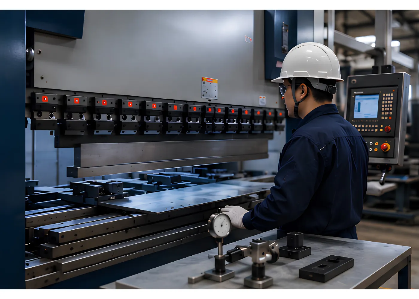
Every BENDORA press brake goes through structured inspection and functional testing before shipment. Key checks cover machine geometry, hydraulic and electrical operation, CNC functions, backgauge positioning and trial bending performance.

100% Pre-Shipment Testing
Each completed machine undergoes functional inspection before it is approved for shipment.

Machine Geometry & Positioning Checks
Critical machine geometry, ram movement and backgauge positioning are checked to support consistent bending operation.

Trial Bending Verification
Final trial bends help verify machine setup, control functions and bending performance under operating conditions.

Engineered Around Your Bending Requirements

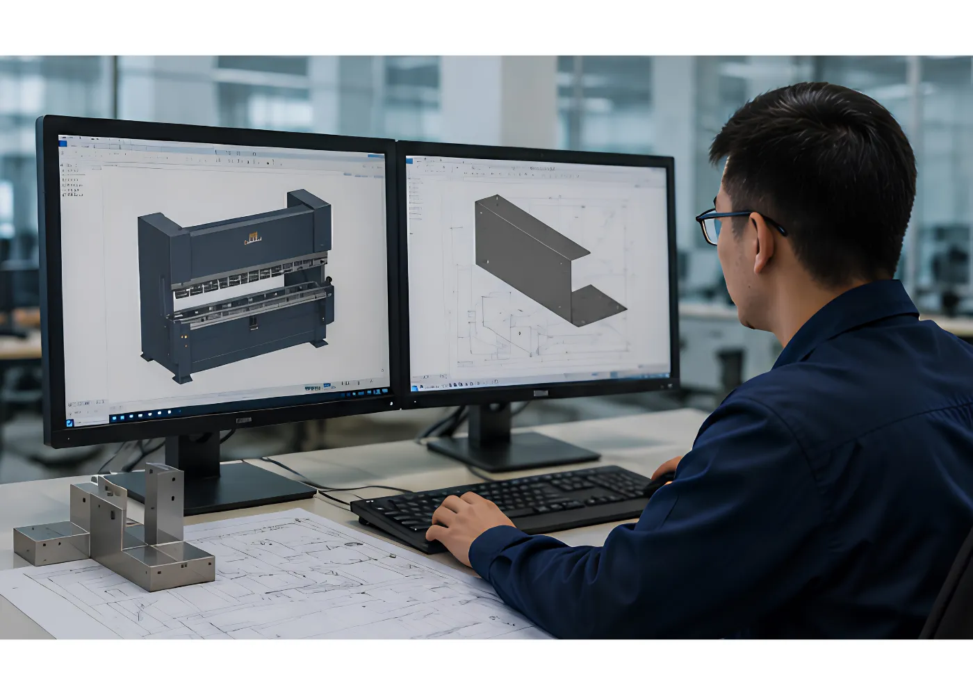
BENDORA configures press brake solutions around material type, thickness, bending length, part geometry and production requirements. CNC control, backgauge, tooling, safety and automation options can be matched to the application.

Application-Based Machine Selection
Bending force, working length and machine configuration are selected around the parts and materials to be processed.

Flexible Machine Configuration
CNC controls, backgauge axes, tooling and safety systems can be configured for different production requirements.

Automation Integration
Options for material handling, robotic bending and other automation can support higher-volume or specialized production.

Support Throughout the Machine Lifecycle

BENDORA provides technical support from machine installation and commissioning through operation and maintenance. Remote troubleshooting, operator guidance and spare-parts support help customers keep their press brake equipment running reliably.

Installation & Commissioning Support
Technical guidance supports machine installation, setup, commissioning and initial production preparation.

Remote Technical Assistance
Remote troubleshooting and operating guidance help identify machine, CNC and process-related issues when support is needed.

Spare Parts & Maintenance Support
Replacement parts and maintenance guidance support long-term machine operation and help reduce unnecessary downtime.

2-Year Warranty
Machine warranty coverage
24/7 Remote Support
Technical assistance when needed

Precision Bending Solutions for Flexible Sheet Metal Production

BENDORA CNC Hydraulic Press Brakes combine CNC-controlled positioning, electro-hydraulic synchronization and rigid machine construction for consistent sheet metal bending across different production requirements.

The current series includes configurations from 110 t to 220 t and 3,200 to 4,000 mm of bending length. Machine selection should consider bending force, working length, material, tooling and part geometry together rather than relying on tonnage alone.

CNC Hydraulic Press Brake Models

BENDORA’s CNC hydraulic press brake series provides three configurations with different combinations of bending force and working length.

ModelBending ForceBending LengthTypical Application Positioning
BH-11032110 t3,200 mmGeneral sheet metal bending
BH-17032170 t3,200 mmHigher forming capacity
BH-22040220 t4,000 mmHigher force and longer working length

BH-11032

110 t × 3,200 mm

A balanced configuration for general sheet metal bending where a 3,200 mm working length and 110 t bending force meet the requirements of the application.

  • CNC-controlled backgauge
  • Electro-hydraulic synchronization
  • 110 t bending force
  • 3,200 mm bending length

BH-17032

170 t × 3,200 mm

A higher-capacity option for applications requiring greater forming force while maintaining a 3,200 mm working length.

  • CNC-controlled backgauge
  • Electro-hydraulic synchronization
  • 170 t bending force
  • 3,200 mm bending length

BH-22040

220 t × 4,000 mm

A higher-force configuration with a longer working length for applications involving larger workpieces or greater forming requirements.

  • CNC-controlled backgauge
  • Electro-hydraulic synchronization
  • 220 t bending force
  • 4,000 mm bending length

If you are unsure which configuration matches your application, provide the material type, thickness, bending length and part drawing so the machine requirements can be evaluated more accurately.

How a CNC Hydraulic Press Brake Works

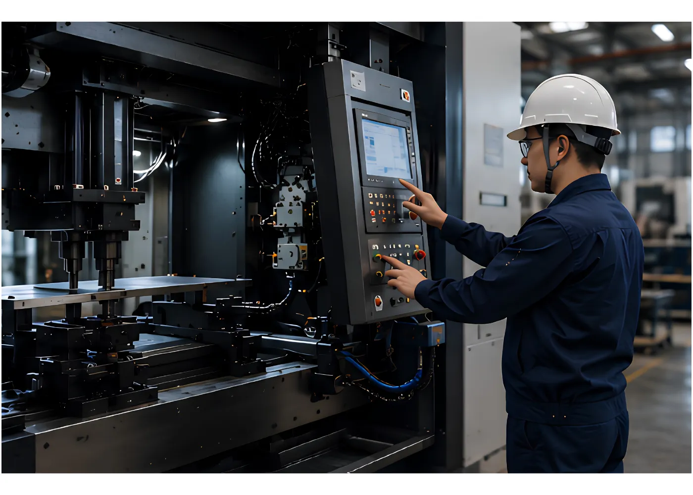
A CNC hydraulic press brake uses hydraulic force to move the ram and form sheet metal between a punch and die. The CNC system coordinates programmed machine movements and workpiece positioning so established bending sequences can be reproduced more consistently.

The main systems work together as one forming process:

Machine Frame → Hydraulic System → Ram → Tooling → Backgauge → CNC Control

The frame provides the structural foundation. The hydraulic system generates and controls forming movement, while the tooling shapes the material and the CNC-controlled backgauge establishes repeatable workpiece positioning.

For buyers, the important question is not simply whether a machine has CNC control. Its force, working length, tooling and positioning configuration need to match the parts being produced.

How to Choose the Required Press Brake Capacity

The required bending force depends on several interacting variables:

  • Material type
  • Material thickness
  • Bending length
  • V-die opening
  • Bending method
  • Material strength
  • Bend geometry
  • Required bend radius

A practical selection sequence is:

Material → Thickness → Bending Method → V-Die → Required Force → Machine Tonnage

This provides a more useful starting point than selecting a press brake based only on the maximum material thickness expected in production.

Bending Force and Material Thickness

Technical references supplied for this project give the following simplified relationship for SS material:

P = 68 × t² ÷ V

under the stated conditions, with the result expressed in tons per meter.

The important engineering relationship is that bending force increases with the square of material thickness, decreases as V-die width increases, and varies with material strength.

This formula should be treated as an initial reference rather than a universal machine-sizing formula. Actual selection should consider material, thickness, bending length, tooling and bending method together.

Bending Length Is a Separate Selection Factor

Bending force and bending length describe different machine requirements.

Bending force determines the forming capacity available to deform the material.

Bending length determines the practical working width available for the component.

BENDORA’s current CNC hydraulic series covers:

ModelBending ForceWorking Length
BH-11032110 t3,200 mm
BH-17032170 t3,200 mm
BH-22040220 t4,000 mm

A machine can have sufficient tonnage but still be unsuitable if its working length does not accommodate the required part.

Likewise, selecting a substantially larger machine than necessary may add equipment cost and floor-space requirements without providing a corresponding production benefit.

V-Die Selection Affects the Bending Process

The V-die opening influences how the material is formed and how much force the operation requires.

It affects:

  • Bending force
  • Bend radius
  • Minimum flange dimensions
  • Material deformation
  • Tool-to-material contact
  • Finished geometry

Technical references use different V-die relationships for free bending, bottom bending and corrective bending. The appropriate opening therefore depends on material, thickness, bending method, tooling and part geometry.

The goal is not to select the largest or smallest V-die, but one that supports the required bend while remaining appropriate for the material and machine capacity.

Selecting the Right Bending Method

Different bending methods involve different relationships between flexibility, force and angle control.

Air Bending

Air bending allows different bend angles to be produced through controlled ram movement and material deformation. It provides flexibility, but the final angle can be influenced by material properties, machine conditions and springback.

Bottom Bending

Bottom bending brings the material more closely into contact with the die profile. It can provide good angle consistency under suitable conditions, although springback still needs to be considered.

Corrective or Coining-Type Bending

Corrective bending applies substantially higher pressure to produce a more controlled bend and can support smaller bend radii. The trade-off is a significantly higher force requirement, making machine capacity and tooling particularly important.

No single method is best for every application. The appropriate process depends on material, geometry, required accuracy, tooling and production conditions.

What Affects Bending Accuracy?

Springback occurs when the material partially returns toward its original shape after forming pressure is released.

Its magnitude is affected by material properties, thickness, bend radius and forming conditions. The technical references supplied for this project indicate that, under comparable conditions, stainless steel tends to show more springback than cold-rolled steel, while thinner material can also show greater springback.

This is why bending accuracy should not be attributed to the CNC controller alone.

A more complete model is:

Machine Structure + Hydraulic Control + Positioning + Tooling + Material + Process

Springback can be managed through appropriate tooling, bend radius, bending method, CNC positioning, process adjustment and test bending. In production, establishing and repeating a suitable process can be as important as the machine’s nominal specification.

CNC Backgauge for Repeatable Positioning

The backgauge establishes the workpiece position before each bend.

Accurate positioning affects the location of the bend and the relationship between multiple bends on the same component. For repeated production, consistent positioning can reduce manual adjustment and make established bending sequences easier to reproduce.

BENDORA’s CNC hydraulic press brake models use CNC-controlled backgauges as part of their configuration.

The production value of a CNC backgauge is therefore not simply faster movement. It is the ability to make workpiece positioning more repeatable.

Electro-Hydraulic Synchronization

BENDORA CNC hydraulic press brakes use an electro-hydraulic synchronized system to coordinate ram movement during forming.

Synchronization helps maintain controlled movement across the working width, providing a stable foundation for consistent bending conditions.

This becomes particularly important when bending across a substantial portion of the machine’s working length or when repeated production requires consistent forming behavior.

Tooling Is Part of the Bending System

The press brake cannot be evaluated separately from its tooling.

Punches and dies determine how the material is contacted and formed, affecting:

  • Bend angle
  • Bend radius
  • Required force
  • Flange geometry
  • Surface quality
  • Setup efficiency
  • Tool life

For surface-sensitive materials, die contact deserves particular attention. Sliding contact can create scratches, while unsuitable tooling conditions can affect the appearance of finished parts.

Depending on the application, appropriate die geometry, surface treatment, lubrication or protective tooling can help reduce marking.

When Specialized Tooling Makes Sense

Specialized tooling can provide practical benefits for applications involving:

  • Hemming
  • Step or Z bending
  • Small flanges
  • Complex profiles
  • Surface-sensitive materials
  • Frequent tooling changes

The technical references also describe long-life hardened tooling designed to reduce wear and regrinding requirements, as well as quick-clamping solutions intended to reduce setup time.

The objective is not to add every available tooling option. It is to select tooling according to the geometry, surface requirements and production workflow.

Common Bending Problems

Surface Scratches

Sliding contact between the sheet and die is a common source of scratches.

Depending on the material and surface requirements, possible measures include increasing the die shoulder radius, improving surface conditions, lubrication or using dedicated scratch-prevention tooling.

Cracking at the Bend

Cracking can be related to material direction, bend radius and sheet-edge condition.

The supplied technical references indicate that bending parallel to the rolling direction can increase cracking risk in some materials. Increasing the inside radius and considering material orientation can help reduce this risk.

Inconsistent Bend Angles

Angle variation may result from material properties, springback, tooling, positioning or machine conditions.

A controlled CNC process combined with suitable tooling and process adjustment can improve repeatability.

Edge or Profile Interference

Some formed geometries can create protrusions that interfere with later assembly.

Depending on the component, the solution may involve modifying the part design, adding a process feature or selecting tooling that better accommodates the geometry.

Choosing the Right BENDORA Configuration

The three current CNC hydraulic configurations provide different combinations of force and working length.

BH-11032 — 110 t × 3,200 mm

A starting point for general applications requiring a balanced combination of bending force and working length.

BH-17032 — 170 t × 3,200 mm

A higher-force option when the application requires more forming capacity without increasing the working length beyond 3,200 mm.

BH-22040 — 220 t × 4,000 mm

A higher-capacity option when both greater forming force and a longer working length are required.

These are starting points rather than universal application limits. Final selection should consider material, thickness, bending length, V-die, bend geometry and production requirements.

If you need help determining the appropriate capacity, provide the material, thickness, bending length and part drawing for evaluation.

Press Brake Selection Checklist

Before requesting a quotation, prepare:

  • Material type
  • Material thickness
  • Maximum bending length
  • Part dimensions
  • Bend angles
  • Required bend radius
  • Production volume
  • Number of bends
  • Surface-finish requirements
  • Part drawing, if available
  • Special tooling requirements

The more complete the application information, the more accurately the required machine capacity and tooling can be evaluated.

Applications

CNC hydraulic press brakes support a broad range of sheet metal forming operations.

General Metal Fabrication

For formed sheet components, brackets, covers and fabricated assemblies.

Industrial Equipment

For machine housings, structural components and formed panels.

Electrical Enclosures

For cabinets, panels and other sheet metal enclosures.

Construction Components

For formed metal components used in construction and related fabrication.

Automotive Manufacturing

For sheet metal components requiring repeatable forming.

The appropriate machine configuration depends on the material, part geometry, bending force and production requirements of the application.

BENDORA Manufacturing and Quality Support

A press brake is a long-term production investment, so supplier capability should be considered alongside machine specifications.

BENDORA Machinery has 15+ years of industry experience, operates a 32,000 m² manufacturing facility, and has an annual production capacity of 1,200+ machines. BENDORA serves customers across 45+ countries with support from a team of 30+ engineers.

Every machine undergoes 100% pre-shipment testing before delivery. BENDORA also provides a 2-year warranty and 24/7 remote technical support, with CE conformity and ISO 9001 included among its stated compliance and quality credentials.

These capabilities give buyers additional information when evaluating both the equipment and the supplier behind it.

Request a CNC Hydraulic Press Brake Recommendation

The right press brake starts with the part you need to make.

Send BENDORA your material, thickness, bending length, part dimensions and drawing, and our team can evaluate the relevant bending force, machine configuration and tooling requirements for your application.

FAQ


How do I choose the right CNC hydraulic press brake?

Start with material type, thickness, maximum bending length, bend geometry and production requirements. These factors determine the required bending force, working length and tooling configuration.

Tonnage depends on material strength, thickness, bending length, V-die opening and bending method. Technical formulas can provide an initial estimate, but actual machine selection should consider the complete forming condition.

Bending force describes the machine’s forming capacity, while bending length describes the available working width. Both need to match the workpiece.

The V-die opening affects required force, bend radius, flange geometry and material deformation. The appropriate opening depends on material, thickness, bending method and part geometry.

The machine can be configured for different sheet metal applications, but the appropriate capacity and tooling depend on the specific material, thickness and bending requirements.

Add Your Heading Text Here

Lorem ipsum dolor sit amet, consectetur adipiscing elit. Ut elit tellus, luctus nec ullamcorper mattis, pulvinar dapibus leo.