Press brake safety depends on more than PPE or knowing where the emergency stop is located. Safe bending combines point-of-operation guarding, correctly installed tooling, controlled machine movement, operator training, inspection, and safe maintenance procedures.
The punch and die create the most obvious crushing hazard, but operators also face risks from moving workpieces, backgauges, heavy tooling, unexpected machine activation, and stored energy. Understanding these hazards and the limits of each safeguard is the foundation of safe press brake operation.
Why Is Press Brake Safety Important?
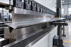
A press brake applies concentrated force along a bending line. During the closing stroke, the space between the punch, workpiece, and die becomes a point-of-operation hazard where hands or fingers can be severely injured.
Long sheets can also rise during bending, fingers can become trapped around backgauges or tooling ends, and heavy punches and dies can shift or fall during setup.
| Hazard Area | Main Risk | Typical Control |
|---|---|---|
| Punch and die | Crushing or amputation | Light curtain, laser guard, two-hand control |
| Tooling ends | Pinching or crushing | Side guards, controlled access |
| Backgauge | Finger pinch points | Safe positioning and training |
| Moving workpiece | Striking or trapping | Sheet supports, controlled handling |
| Tool installation | Falling or shifting tooling | Secure clamping, handling aids |
| Maintenance | Unexpected movement | Energy isolation and LOTO |
PPE can reduce some secondary injuries, but it cannot replace engineering controls that prevent exposure to dangerous machine movement.
Press Brake Safety Standards You Should Know
Safety requirements vary by machine, application, workplace, and jurisdiction. Employers should follow applicable regulations, manufacturer instructions, and machine-specific risk assessments.
OSHA Machine Guarding Requirements
In the United States, OSHA 29 CFR 1910.212 requires machinery to be guarded where the point of operation exposes employees to injury. For press brakes, the objective is to prevent personnel from entering the danger zone during a hazardous operating cycle.
Safeguarding may include barrier guards, two-hand controls, electronic safety devices, or other appropriate measures based on the actual hazard and machine configuration.
ANSI B11.3-2022 and Safe Distance
ANSI B11.3-2022, Safety Requirements for Power Press Brakes, is the current ANSI standard specifically addressing power press brake safety.
OSHA has historically recognized safe-distance methods for certain operations under defined conditions. However, these historical provisions should not be treated as a universal substitute for engineered point-of-operation safeguarding or as a summary of ANSI B11.3-2022.
International Press Brake Safety Standards
ISO 6909:2026, Machine Tools — Safety — Press Brakes, specifies technical safety requirements primarily for the design, manufacture, and supply of several types of press brakes, including hydraulic and servo-driven configurations.
Applicable requirements still vary by machine design and jurisdiction, so users and manufacturers should verify the standards relevant to their specific equipment.
Understand the Main Press Brake Danger Zones
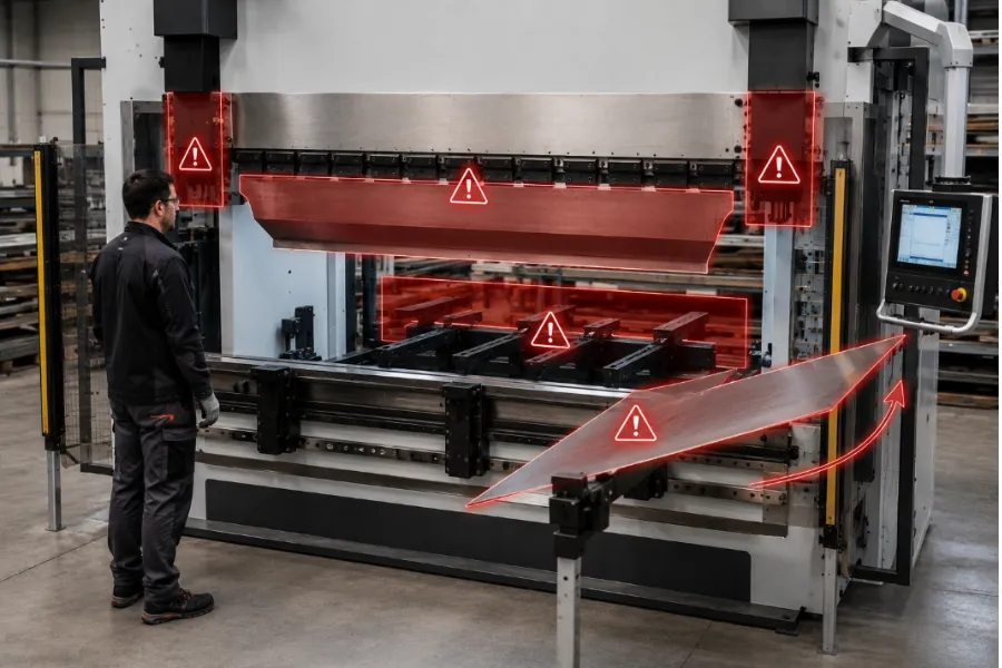
Effective press brake safety begins with identifying where injuries can occur. Focusing only on the front of the punch and die can leave secondary hazards uncontrolled.
Punch and Die Closing Zone
The primary hazard occurs where the punch approaches the material and lower die. Hands should remain outside this zone whenever hazardous movement is possible because reaction time cannot be relied upon to escape closing tooling.
Side Gaps and Backgauge Area
Front-mounted protection does not necessarily protect access around tooling ends or between the tooling and machine frame. Side guarding or interlocked protection may therefore be necessary.
The CNC backgauge also creates potential pinch points. Operators should understand programmed axis movement and avoid placing fingers between the sheet, backgauge fingers, supports, and other moving components.
Workpiece Movement Zone
Long sheets can rise rapidly as a bend develops, while large or heavy parts may shift or fall if inadequately supported.
Operators should anticipate workpiece movement before initiating a bend. Sheet supports, lifting assistance, or coordinated handling may be appropriate for larger parts.
Press Brake Guarding and Safety Devices
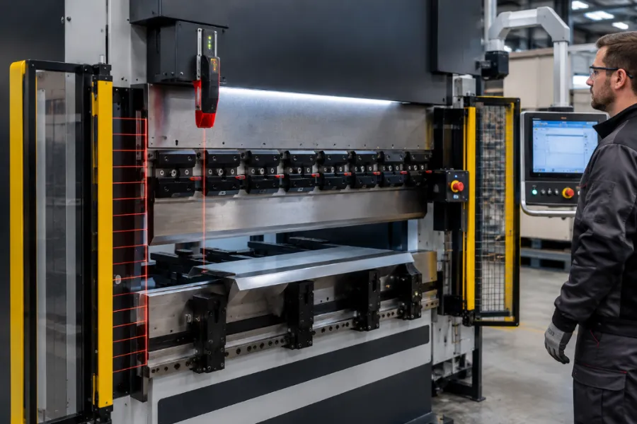
No single safety device protects every area of a press brake. Guarding should reflect the machine, tooling, part geometry, bending sequence, and operator access.
Light Curtains
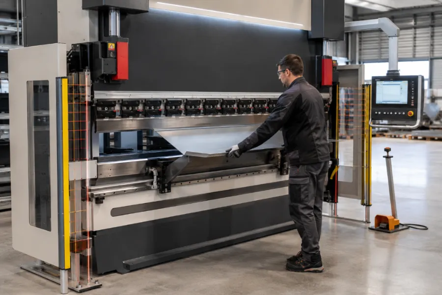
Light curtains create a sensing field that can initiate a stop when interrupted during hazardous machine movement.
Their protection has boundaries. A front light curtain does not automatically protect side or rear access, while blanking or muting must not create an uncontrolled path into the danger zone.
Laser Guarding Systems
Press brake laser guards monitor the area close to the punch. Their effectiveness depends on ram position feedback, stopping performance, muting parameters, control architecture, and tooling geometry.
Tool changes can alter these conditions, so safeguarding parameters may need to be reviewed after different tooling or part geometries are introduced.
Two-Hand Controls and Physical Guards
Two-hand controls keep both of the operator’s hands occupied during the relevant portion of the cycle, but they do not automatically protect other workers who can access the point of operation.
Physical and interlocked guards can restrict side, rear, or other hazardous access not covered by optical devices.
Emergency Stops
Operators should know the location and function of emergency stops, and their operation should be included in appropriate machine checks.
An E-stop does not replace point-of-operation guarding. Safeguarding is intended to prevent or interrupt hazardous exposure before an injury occurs.
Why Stopping Time and Safety Distance Matter
A presence-sensing device only protects an operator if the press brake can stop before the person reaches the danger zone:
Ram speed → stopping time → stopping distance → safeguarding position
Stop-Time Measurement (STM) determines how long the machine actually takes to stop after receiving a stop command. Actual stopping performance can support the positioning and validation of safeguarding systems.
Stopping performance may change as hydraulic valves, seals, controls, and other components age. Original factory data should therefore not automatically be assumed to represent the machine’s current condition.
Periodic verification and documentation can help identify changes and determine whether the safeguarding configuration remains appropriate.
Safe Press Brake Tooling Installation
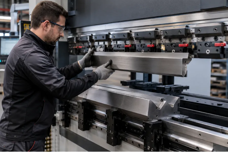
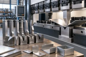
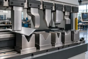
Tooling safety starts before production. Incorrect installation can allow heavy tooling to fall, create misalignment, or expose punches and dies to uneven loading.
Inspect Tooling Before Installation
Inspect punches and dies for cracks, deformation, damaged surfaces, excessive wear, and corrosion. Tooling with cracks or serious damage should not remain in service.
Wear on punch tips and die shoulders can gradually affect bending accuracy and load distribution, while progressive corrosion can damage tooling surfaces and reduce reliability.
Install and Secure the Tooling
Mounting surfaces should be clean and secure. Follow the installation and spacing requirements of the specific tooling and clamping system.
Heavy upper tooling should be installed using its intended mounting method and suitable handling assistance where necessary. After installation, check alignment under controlled conditions, complete the required clamping sequence, release pressure slowly, and verify that the tooling has not loosened or moved.
Check Tooling Capacity Before Bending
Machine tonnage and tooling capacity are not the same. A press brake may have sufficient overall capacity while the selected punch, die, or holder cannot safely carry the required load.
Bending force is influenced by material strength, thickness, bend length, and V-die opening. Tool capacity should therefore be compared with the actual load created by the bending setup.
Tonnage charts also have defined assumptions. Values based on mild steel should not automatically be applied to stainless or high-strength steel without accounting for different material and bending conditions.
Before production, confirm both the required bending force and the allowable load of the complete tooling configuration.
Safe Press Brake Operating Procedure
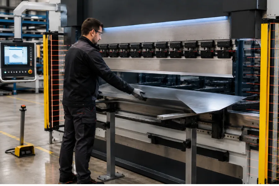
Consistent procedures help prevent small setup errors from developing into serious hazards.
Before Bending
Inspect the machine for leaks, loose components, damage, or abnormal conditions. Verify guarding, E-stops, foot controls, tooling, the correct program, and the workpiece setup.
The operator should also understand how the workpiece and backgauge will move during the bending sequence.
During Bending
Keep hands outside the danger zone and never reach into the tooling to reposition a part while hazardous movement is possible.
Watch the workpiece as well as the tooling. Long sheets can rise during bending, while backgauges and supports may reposition automatically.
For multi-operator work, clearly define who controls machine initiation. Safety devices should never be bypassed to prevent production interruptions; repeated false trips should trigger investigation of the setup or safeguarding system.
After Bending
Allow the ram and workpiece to reach a safe position before removing or repositioning the part.
If the machine produces abnormal noise, faults, unexpected movement, or evidence of tooling displacement, stop operation and investigate before continuing.
Tool Changes, Jam Clearing, and LOTO
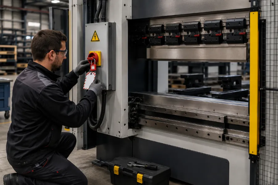
Tool changes can alter punch height, part geometry, muting positions, and access to the danger zone. Relevant safety functions should therefore be verified after a tooling change rather than assuming the previous configuration remains valid.
A jammed workpiece should not be pulled from the die while hazardous machine movement remains possible. Where jam clearing, servicing, or maintenance exposes workers to unexpected startup or hazardous stored energy, applicable energy-isolation and Lockout/Tagout (LOTO) requirements should be followed.
Electrical, hydraulic, pneumatic, gravitational, and other stored energy may remain after normal controls are switched off. An emergency stop is not the same as verified energy isolation.
Specific LOTO requirements depend on the task and applicable regulations, including limited exceptions for qualifying minor servicing activities with effective alternative protection.
PPE for Press Brake Operators
PPE provides an additional layer of protection but does not replace press brake guarding.
Appropriate eye protection can protect against flying particles, while safety footwear may be required where falling or rolling objects create foot hazards. Hearing protection should be selected according to workplace noise exposure.
Cut-resistant gloves can help when handling sharp sheet metal or tooling, but hand protection should be selected according to the task and identified hazards. Loose clothing, jewelry, lanyards, and other items that could become caught should be kept away from moving equipment.
Daily Press Brake Safety Checklist
Before starting a shift or new setup, confirm that:
- Guards and interlocks are installed and functional.
- Light curtain or laser safeguarding works correctly where equipped.
- Emergency stops and cycle controls function correctly.
- Foot pedals are undamaged and operate normally.
- Punches and dies have no cracks, serious wear, corrosion, or damage.
- Tooling is correctly aligned and securely clamped.
- No hydraulic leaks or abnormal machine conditions are present.
- The work area is clean and unobstructed.
- The correct program, tooling, and workpiece setup are confirmed.
- Required PPE and material-handling equipment are available.
If a safety-critical device fails inspection, normal production should not continue until the problem is properly corrected.
Common Press Brake Safety Mistakes
Common mistakes include bypassing guards, reaching into the die area, using damaged tooling, and assuming that slow ram movement eliminates the crushing hazard.
Another mistake is relying on old safety settings after tooling changes or machine aging. Muting parameters, guarding positions, and stopping performance should reflect the current setup and machine condition.
Repeated safety-device trips should not be “solved” by widening blanking zones or disabling protection. They may indicate that the safeguarding system, tooling configuration, or stopping performance needs reassessment.
Building a Safer Press Brake Operation
Press brake safety should be considered when selecting and configuring a machine, not added only after installation. Buyers should evaluate point-of-operation protection, side and rear guarding, tooling-change procedures, safety documentation, and operator training.
Part geometry, material handling, tooling, production volume, and operator access all influence the appropriate safeguarding solution.
BENDORA evaluates press brake applications according to material, thickness, bending length, tooling, part geometry, production requirements, and operating conditions. These variables help define the machine configuration and safeguarding considerations that should be discussed before equipment selection.
Conclusion
Effective press brake safety combines hazard identification, point-of-operation guarding, verified stopping performance, correctly installed tooling, disciplined operating procedures, energy control, maintenance, training, and appropriate PPE.
The central principle is to control hazardous machine movement before a person can enter the danger zone. When safety measures match the machine, tooling, workpiece, and production process, safety becomes part of how the bending operation is engineered.
For a new press brake project, buyers can provide BENDORA with material type, thickness, bending length, part drawings, tooling requirements, production volume, and operating conditions so that relevant machine and safeguarding requirements can be evaluated together.
Press Brake Safety FAQ
What Is the Biggest Hazard When Operating a Press Brake?
The primary hazard is the point of operation where the punch, workpiece, and die come together. Other risks include moving workpieces, backgauges, side access points, heavy tooling, sharp sheet edges, and stored energy.
What Safety Devices Are Used on Press Brakes?
Common systems include light curtains, laser guards, two-hand controls, physical guards, interlocks, emergency stops, and safety-related machine controls. The appropriate combination depends on the machine, tooling, application, and applicable safety requirements.
Can a Press Brake Operate Without a Light Curtain?
A light curtain is one safeguarding method, not the only possible solution. Whether another method is appropriate depends on the machine, operation, risk assessment, and applicable safety requirements.
What PPE Should a Press Brake Operator Wear?
PPE may include eye protection, safety footwear, task-appropriate hand protection, and hearing protection where required. PPE should be selected through a workplace hazard assessment and does not replace machine guarding.
When Is LOTO Required on a Press Brake?
LOTO generally applies when servicing, maintenance, jam clearing, or tool-related work exposes personnel to unexpected startup or hazardous stored energy. Exact requirements depend on the task and applicable energy-control rules.